EE 212L: Negative and General Impedance Converters
Objective: This lab demonstrates two novel uses of op-amps: Negative Impedance Converters (NICs) and Generalized Impedance Converters (GICs). As the name implies, a NIC enables an equivalent impedance of opposite sign to that included in the circuit (e.g., resistance to negative resistance or capacitor to inductor). The GIC enables impedances to be achieved with values that may be difficult to attain with passive components. For example, a GIC can convert a capacitor to inductor and vice versa, scale an impedance, and represent a negative resistance. These circuits are assumed to be in sinusoidal steady-state and can be analyzed using frequency-domain (AC) methods.
Pre-lab:
- Analyze the circuit in Figure 1 to show that it is a negative impedance converter, i.e., show that Zin = Vin/Iin = -Z.
- Given that an RL circuit (see Figure 4) might be a good way to verify that an inductor has been "made" out of a NIC or GIC, what two tests could be run on the circuit to verify the value of inductance? Find key values for these tests such that they can be validated experimentally in the lab. Hint: step inputs and time constants or sinusoidal inputs and phase shifts are options as time constants and phase shifts will depend on the inductance.
- Analyze the circuit of Figure 2 in the lab to show that its input impedance is Zin = Z1 Z3 Z5 / (Z2 Z4). Verify that if Z2 or Z4 is a capacitor and the other impedances are resistors, then Zin is the impedance of an inductor.
Laboratory Procedure:
- Negative-Impedance Converters
- The NIC shown in Figure 1 uses an op-amp and resistors to
produce an input impedance of Zin = -Z. Design and
build a NIC with Zin = -10kΩ. Choose the
resistors R to keep the op-amp supply current from exceeding its
maximum for the rated range of input voltages. Also keep in mind
that the op-amp circuit only acts as a NIC so long as it is not
operating in saturation.
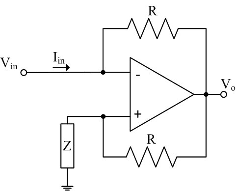
Figure 1: Negative Impedance Converter (NIC) circuit - Put a voltage source and two 10kΩ resistors in series with your -10kΩ NIC and take measurements to verify that the NIC really behaves as -10kΩ.
- The NIC shown in Figure 1 uses an op-amp and resistors to
produce an input impedance of Zin = -Z. Design and
build a NIC with Zin = -10kΩ. Choose the
resistors R to keep the op-amp supply current from exceeding its
maximum for the rated range of input voltages. Also keep in mind
that the op-amp circuit only acts as a NIC so long as it is not
operating in saturation.
- General Impedance Converters
- Figure 2 shows a GIC which is built using two op-amps and five
impedances. The input impedance of a GIC is given by
Z1 Z3 Z5/(Z2
Z4).
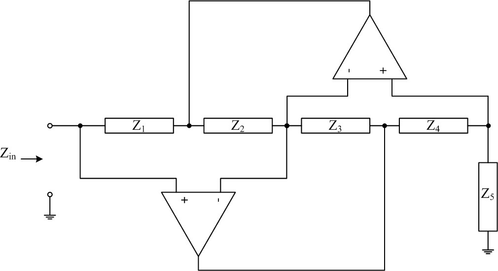
Figure 2: General Impedance Converter (GIC) circuit - Build a GIC to simulate (act as) a 10kΩ resistor using two op-amps and five resistors.
- Use this simulated resistor in series with a real 10kΩ
resistor to build a voltage divider as shown in Figure 3. Drive
the voltage divider with a 1kHz, 2V peak-to-peak sine wave. Does
the voltage across your simulated resistor look like what you
would expect?
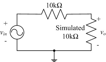
Figure 3: Voltage divider circuit - A typical use of GICs is to simulate inductors. If Z2 or Z4 is a capacitor and the other impedances are resistors, then Zin is the impedance of an inductor. GICs are used to simulate inductors because it is virtually impossible to build an inductor as part of an integrated circuit, whereas op-amps, capacitors and resistors are relatively easy to incorporate. Modify your GIC such that it acts like a 10H inductor.
- Use your simulated 10H inductor in the RL circuit shown in Figure 4 and run one, or both, experiments that you planned in the pre-lab to verify its value. Compare the measured value of your simulated inductor to the desired value.
- Increase the amplitude of the input voltage until the output
becomes distorted. Why does the response of the circuit with the
simulated inductor depart from the ideal response?
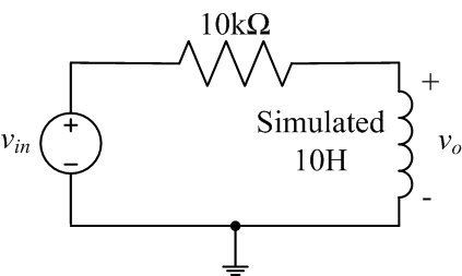
Figure 4: Series RL circuit
- Figure 2 shows a GIC which is built using two op-amps and five
impedances. The input impedance of a GIC is given by
Z1 Z3 Z5/(Z2
Z4).
Revised APR2015