In this lab you will design a simple control system that reacts to an input signal and produces a desired behavior based on this signal. For example, if you are trying to control the temperature of a computer, you will need to measure the temperature, and if the temperature is above a certain value, turn on a fan to cool it off. If the temperature drops below a certain value, turn off the fan. Hence, you control the temperature of the computer using an input signal (temperature) through an output signal controlling the fan.
The control system that you will design is going to be implemented on the computer that you build previously. Since the computer is a digital system, it can't handle continuous signals, neither in time nor in value as that requires infinitely fast computer as well as infinite precision to represent the infinite possibilities of the values of the input signal. Therefore, we need to sample the input signal, i.e., pick only fixed points in time rather than all time. We also need to digitize those sampled values and represent them by finite binary values. This process is accomplished using a analog-to-digital converter (ADC).
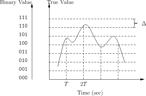
Figure 1 is an example of sampling and digitizing of a continuous signal. First, the signal value is captured at a fixed point in time, then this value will be approximated to the closest digital level available. In this case, each value is represented using only 3 bits and therefore there is only 8 different digital values as opposed to the infinite values that can be represented by the continuous signal.