next up previous
Up: Lab 11: Control System Previous: Lab 11: Control System

1 Lab

  1. If your ADC is 8-bits, how many digital levels do you have? What is the resolution of this ADC if it operates in the range of 0-5V, e.g. looking at Figure 1, what is $ \Delta$ in volts?. If the input is 2.5V, what is the output?
  2. Build the circuit shown in Figure 2.
    Figure 2: ADC0804 Tester
    \includegraphics{adc_tester.eps}

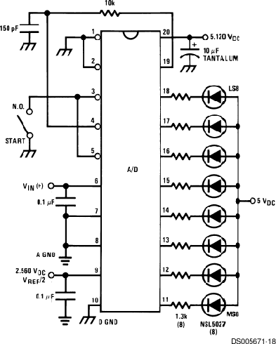
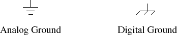
    Make sure to have separate buses for the analog ground and the digital ground (See Figure 3). Then connect them at a single point on your board. Otherwise, there will be noise on the analog signals due to the fast switching of the digital portion of the chip. Datasheet of ADC0804.

    Figure 3: Analog and digital ground symbols
    \includegraphics{grounds.eps}

  3. Use a variable pot to control the input to the ADC. Connect the output to the LEDs on your protoboard. Verify that it works properly.
  4. Design a computer program that takes in the value for the ADC and if it is greater than 2.5V then output a 1, otherwise output a 0.
  5. Implement your control system and verify its operation in hardware as shown in Figure 4.
    Figure 4: System overview with the variable resistor represents the variable output of a temperature sensor.
    \includegraphics[width=\textwidth]{system_overview.eps}

next up previous
Up: Lab 11: Control System Previous: Lab 11: Control System
Copyright © 2008, Electrical Engineering Department, New Mexico Tech
Last Modified 2009-11-18