next up previous
Next: 2 Lab Up: Lab 4: Adder/Subtractor Previous: Lab 4: Adder/Subtractor

1 Prelab

  1. Write the truth table for a full adder.
  2. Write the truth table for a full subtractor.
  3. Show how you can use half adders to build a full adder.
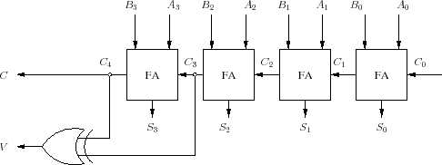
  4. Figure 1 shows how to implement a ripple adder using a sequence of 1-bit full adders. Using an example, verify that this circuit functions as a 4-bit adder.
    Figure 1: 4-bit adder
    \begin{figure}\begin{center}
\scalebox{0.65}{
%
\input{adder.pstex_t}}
\end{center} \end{figure}
  5. What does the $ V$ signal, which may be computed as $ V=A_3B_3S_3'+A_3'B_3'S_3$ , represent? In order to answer this question try to use examples when you are adding two positive numbers and another when you are adding two negative numbers.
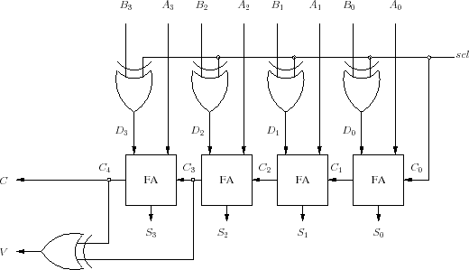
  6. By slightly modifying the circuit shown in Figure 1 we can design an adder/subtractor as shown in Figure 2. Why does this circuit makes and adder when the sel is 0, and why does it behave as a subtractor when the sel is 1.
    Figure 2: 4-bit adder/subtractor
    \begin{figure}\begin{center}
\scalebox{0.65}{
%
\input{adder-subtractor.pstex_t}}
\end{center} \end{figure}
  7. Fill Table 1

    Table:
    sel Input $ B$ Output $ D$ in terms of $ B$
    0 $ B_3B_2B_1B_0$  
    1 $ B_3B_2B_1B_0$  


  8. Using Table 1, write a Verilog program to implement a decoder that selects the proper input to the full adder depending on the sel signal.

next up previous
Next: 2 Lab Up: Lab 4: Adder/Subtractor Previous: Lab 4: Adder/Subtractor
Copyright © 2008, Electrical Engineering Department, New Mexico Tech
Last Modified 2009-09-23