EE 101
Pre-Lab Exercise 1
ALL PRE-LAB AND LAB EXERCISES MUST BE COMPLETED IN A COMP BOOK!
NO ANSWERS ARE COMPLETE WITHOUT THE UNITS!!
Resistor Color Codes --- Note: carbon composition resistors will be used
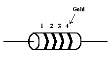
1 2 3 4 (tolerance)
Black |
0 |
0 |
x |
1
|
|
Brown |
1 |
1 |
x |
10
|
|
Red |
2 |
2 |
x |
100
|
2%
|
Orange |
3 |
3 |
x |
1,000
|
|
Yellow |
4 |
4 |
x |
10,000
|
|
Green |
5 |
5 |
x |
100,000
|
|
Blue |
6 |
6 |
x |
1,000,000
|
|
Violet |
7 |
7 |
x |
10,000,000
|
|
Gray |
8 |
8 |
x |
100,000,000
|
|
White |
9 |
9 |
x |
1,000,000,000
|
|
Gold |
|
|
|
|
5%
|
Silver |
|
|
|
|
10%
|
No
band |
|
|
|
|
20%
|
1. Using the resistor color code chart above, list the three colors (in proper
order) that would be found on the following resistors:
a. 23,000 ohms
b. 670 ohms
c. 1,000 ohms
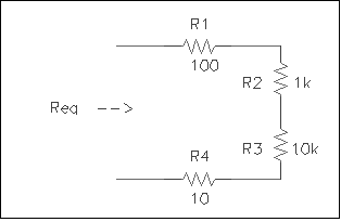
2. Determine the equivalent resistance, Req, for this network.
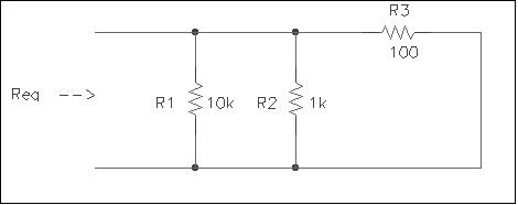
3. Determine the equivalent resistance, Req, for this network.
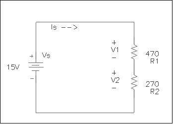
4. Using your knowledge of Kirchoff’s Voltage Law and Ohm’s Law,
calculate the values for Ia and Ib. With this information and Kirchoff’s Current Law,
determine the value for Is.

5. Determine the value of Is. Using this information, calculate values for V1 and
V2.
(end of pre-lab)
EE 101 Lab Exercise 1: Resistors
1. Take the resistors out of their bag. Make sure there are 8 of them. Make a chart
with headings like the one below. List each resistor by its color bands (see column
"Resistor Color Bands" below). Using the color code scheme outlined in class,
determine the values for each resistor and write these in the column under "Color
Code Value". When you are through with this, measure the resistor values with a
multimeter (set to ohms). Be sure not to touch the leads on the resistor while you are
measuring its value, because you will, in effect, be adding your own resistance (in
parallel) to that resistor, and this will affect the answer you get. All the resistors in
this lab have a tolerance of 5% (as indicated by the gold band on the end). Indicate
whether or not the resistors are within tolerance in the last column. When you are
finished, put the resistors back in their bag. You will be using these again later in this
lab.
Color Bands Value Measured Value WithinTolerance?
br-blk-r-(gold) 1 KW
?
(yes or no)
Exercises 2 - 5 require you to build circuits on a protoboard. For all of these
circuits, proper breadboarding technique will be expected. This includes using the
built-in runners on the breadboards when applicable, using wire cut to proper lengths, and
using a proper amount of breadboard space. In short, the circuits you build should be
"readable." Any circuit that does not demonstrate proper breadboarding technique
will not be graded.
2. Using resistors and wire, build the circuit from Exercise 2 in the pre-lab.
Power does not need to be applied to this circuit. Use the multimeter to measure the
equivalent resistance (Req) of the circuit. What value do you measure, and
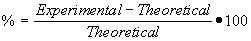
how does this compare to the value we calculated in class? (Perform a percent difference
between the measured value and the expected value of the equivalent resistance.)
3. Follow the instructions from number 2 above for Exercise 3 in the pre-lab.
4. Build the circuit from Exercise 4 in the pre-lab. Ask one of the lab
assistants to check your circuit before applying power to it.
a. Using a voltage meter, measure Ia by measuring the voltage
drop across the resistor, and then calculating the current. Do this first with the meter
probes one way (red/black), then the other (black/red). Write down your answer for Ia
(positive answer). In the same way, measure and record the value of Ib.
b. Now, measure Ia and Ib using a current meter.
Record the values. Are the values you obtained using the current meter significantly
different from the ones you calculated using Ohm’s Law (from part 4a)?
c. How close are your measured currents (using the current meter) to the values
you calculated in the pre-lab (do a percent difference)?
d. Determine the source current (Is) using a current meter. Is Ia
plus Ib equal to Is? What law is demonstrated here?
5. Build the circuit from Exercise 5 in the pre-lab. With the help of the
multimeter, adjust your source voltage to as close to 15V as you can make it. Record the
actual value you measure for Vs. Ask an assistant for help in doing this, if
you need, and as always, ask one of the lab assistants to check your circuit before
applying power to it. With the multimeter, measure V1 and V2.
Do these two values add up to equal the value of your source voltage? What law is
demonstrated here?
Additional question
The equivalent resistance values you measured in 2 and 3 above were probably not
exactly what we had calculated in class. What reasons can you think of for the difference?
|