EE 101 Pre-Lab Exercise 5
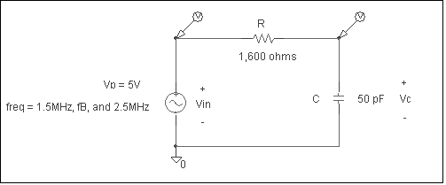
1. What is the transfer function, H(f), (VOUT/VIN) for the circuit? (From Equation 6 in class notes, leave f as a symbol).
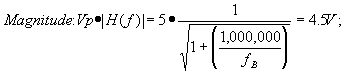
2. What is the half power frequency, fB?
3. What is the magnitude and phase shift angle for Vc (VOUT) at the following frequencies? a. 100 Hz.
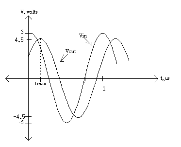
4. Draw a separate plot for each pair of input and output waveforms for 3b, c, and d only. Your graphs should include the input sinusoid (with no phase shift or magnitude degradation) and the output waveform, showing the phase shift and magnitude degradation (if any). Graphs should be fully labeled. As an example, the calculations and graph for a sinusoid with an input frequency of 1 MHz are provided below.
(end of pre-lab) EE 101
Lab Exercise 5: The Low Pass Filter The purpose of this lab is to familiarize the student with the basic characteristics of a first-order low pass filter. Create a PSPICE simulation for the RC circuit in the pre-lab. Use the values given on the schematic for each circuit element. Choose a VSIN element for your source voltage and edit its attributes so that VAMPL = 5v, VOFF = 0 and PHASE = 90. You will need to modify the frequency of this signal with each simulation you run.
1. Simulate the circuit using an input signal frequency of 1.5 MHz.
a. Under the Analysis menu, select the Setup option so that the transient analysis option is checked. After you run your simulation, both the Vin and Vc (Vout) signals should be displayed simultaneously.
b. Using the cursors, measure the amplitudes of Vin and Vc. How do these compare to the values you calculated in the pre-lab exercise for the 1.5 MHz input signal (do a percent difference calculation)?
c. Using the cursors, measure the time delay between a peak on Vin and the next peak on Vc. You may need to choose peaks which occur after the waveforms have "settled" down. Convert this value into degrees. How does this value compare to the phase angle you calculated in the pre- lab exercise for the 1.5 MHz input signal?
d. Label your probe output with your name and the frequency of Vin (1.5 MHz for the first simulation). Then, print out your probe data showing Vin and Vc with the cursors in the position to measure the time shift.
2. Repeat the instructions for 1a - 1d using a 5Vp sinusoid with a frequency of fB for Vin.
3. Repeat the instructions for 1a - 1d using a 5Vp, 2.5 MHz sinusoid for Vin.
Questions: 1. Describe, in general terms, how a low pass filter operates.
2. Write the sinusoidal equations for Vc for parts 1, 2, and 3. They should be of the form
Vc = Vp(cos(2p ft + q ) volts). 3. Let’s assume you are given a few capacitors. Each one has a number printed on it as follows: 105, 223, 471, and 152. What are the values of the capacitors in picofarads? In microfarads? |