EE 101
Pre-Lab Exercise 6
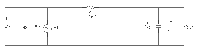
| 1. What is the transfer function, H(f), (VOUT/VIN) for the circuit?
2. What is the half power frequency, fB?
3. What is the magnitude and phase shift angle for Vc (VOUT) at the following frequencies? a. 100 Hz.
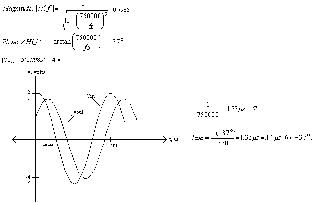
4. Graph a separate plot for each of the output waveforms in 3a, b, c, and d. Your graphs should include the input sinusoid (with no phase shift or magnitude degradation) and the output waveform, showing the phase shift and magnitude degradation (if any). Graphs should be fully labeled. As an example, the calculations and graph for a sinusoid with an input frequency of 750 KHz are provided below.
(end of pre-lab) EE 101
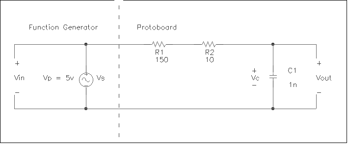
Lab Exercise 6: The Low Pass Filter The purpose of this lab is to familiarize the student with the basic characteristics of a first-order low pass filter.
Figure 1 Build the circuit in Figure 1. Connect the function generator’s output to the circuit. Note that you do not have to use the protoboard’s power supply to excite the circuit. The function generator is providing the voltage source. Like last week, hook one oscilloscope probe (Channel 1) to the red alligator clip coming from the function generator (to measure Vin) and the other oscilloscope probe (Channel 2) to the node that connects the capacitor to the 10W resistor (to measure Vout). Hook both scope ground leads to the black alligator clip on the cable coming from the function generator.
1. Set the function generator to output a 5Vp, 100 Hz sinusoid. a. On your oscilloscope, display both the Vs (Vin) and Vc (Vout) signals simultaneously. (Reminder: Make sure the Channel 2 Invert button is not pressed in. Make sure the volts/division settings are the same for both channels. Also, adjust the ground reference for each channel.) b. Using the cursors, measure the amplitude of Vs and Vc. How do these compare to the values you calculated in the pre-lab exercise for the 100 Hz input signal (do a percent difference calculation). c. Using the cursors, measure the time delay between Vs and Vc. Convert this value into degrees. How does this value compare to the phase angle you calculated in the pre-lab exercise for the 100 Hz input signal? d. Print out your oscilloscope data showing Vs and Vc and the cursors in the position to measure the time shift.
2. Repeat the instructions for 1a - 1d using a 5Vp, 500 KHz sinusoid for Vs.
3. Repeat the instructions for 1a - 1d using a 5Vp sinusoid with a frequency of fB for Vs.
4. Repeat the instructions for 1a - 1d using a 5Vp, 5MHz sinusoid for Vs.
Questions: 1. Describe, in general terms, how a low pass filter operates.
2. Write the sinusoidal equations for Vc for parts 1, 2, 3, and 4. They should be of the form Vc = Vp(cos(2p ft + q ) volts).
3. Let’s say you pick up a few capacitors. Each one has a number printed on it as follows: 105, 223, 471, and 152. What are the values of the capacitors in picofarads? In microfarads? |