Microprocessors communicate with memory and external devices by means of an address bus and a control bus. An address bus is a group outputs (16 for the Motorola 68HC12 we use in EE 308) from the microprocessor that are used to select external devices with which the microprocessor wants to communicate. Think of an address like a post office box number. If Tech wants to send something to you at C/S Box 45123, they will put that address on an envelope and send it to the campus post office. The postal clerk will use that number to decide which box to put the envelope into. If a microprocessor wants to send a message to an external device (e.g. turn on a heater to warm up a room) it will do this by putting the address of the heater on the address bus (e.g. address 0x8000 is meant for the heater). The air conditioner will ignore this address, and will turn on only when its address (e.g. address 0x8800) is specified.
Some devices can only be written to (e.g. a heater which can be turned on or off), or read from (e.g. a temperature sensor which tells the microprocessor the room temperature), while others can be read from and written to (e.g. RAM memory or a disk drive). The control bus is used by the microprocessor to tell the device whether it is being written to or read from.
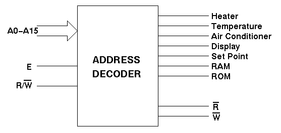
An address decoder is circuitry external to the microprocessor which functions much like the postal clerk -- it looks at the address and decides which device the command is meant for. Below is a diagram of the inputs to and outputs from a typical address decoder for the 68HC12 microprocessor:

Figure 1: Address Decoder for a 68HC12 Microprocessor.
The inputs to the decoder are the address bus (A0 through A15) and the control bus (the E clock and the R/W' line). The outputs from the decoder are chip select signals for individual devices connected to the microprocessor, and read ( R') and write (W') lines to specify the action the microprocessor wants the device to take.
The R' and W' outputs from the decoder should behave as follows: R' should be low when E and R/W' are high; R' should be high otherwise. W' should be low when E is high and R/W' is low; W' should be high otherwise.
The device select outputs should behave as follows: They should all be high
when E is low. When E is high at most one of the outputs will
be low depending on the address and the R/W' inputs (i.e. active
low outputs). Table 1 shows the device selected in the Function column for
a given address (in Hex format) and R/W' state.
| Address | R/W' | Function |
| 0x8000 | Low | Heater |
| 0x8000 | High | Temperature Sensor |
| 0x8800 | Low | Air Conditioner |
| 0x9000 | Low | Temperature Display |
| 0x9000 | High | Temperature Set Point |
| 0xC000 - 0xDFFF | Either | RAM |
| 0xE000 - 0xFFFF | High | ROM |
Table 1 Address map for various devices.
Note that most addresses are not specified -- e.g. address 0x8001 has no function. It is all right if address 0x8001 selects the heater. It is easier (and less expensive) to build the decoder so that it uses a range of address to select a device -- e.g. the range 0x8000 -- 0x87FF to select the heater.
Sept. 2000
Copyright © 2000, New Mexico Tech