The purpose of this lab is to design a quadrature decoder which can be used to accurately determine the angular position of the rotating shaft on a DC motor.
A quadrature encoder/decoder pair is useful in various applications wherein we are interested in determining angular translation (or speed). For example, when using a DC-motor as the drive system for a mobile robot we may wish to move forward (or reverse) by a fixed distance. Knowing the diameter of the drive wheel (and motor gear-ratio) we can calculate the desired angle for the motor drive-shaft to be rotated. A quadrature encoder is typically constructed using a slotted disk with a pair of light emitting diodes (LED's) which are aligned with a pair of photo-transistors (receivers) on the other side of the disk, as illustrated in Figures 1 and 2.
Figure 1: The top-view of an optical encoder.
Figure 2: The side-view of an optical encoder.
Notice that in Figure 1 the A-channel LED has an unobstructed path to transmit light to
the A-channel photo-transistor, thus resulting in a high (i.e. 1) output from the
A-channel photo-transistor, while the B-channel is blocked resulting in a low (i.e.
0) output from the B-channel photo-transistor. As the disk rotates the outputs go
high and low respectively, as shown in Figures 3 and 4.
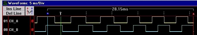
Figure 3: Encoder waveform resulting from clockwise rotation of the motor.
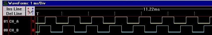
Figure 4: Encoder waveform resulting from counter-clockwise rotation of the motor.
When the motor rotates in a clockwise direction the pattern observed is: CH_A CH_B = ...,00, 10, 11, 01, 00, 10, ... , and in upon counter-clockwise rotation the pattern observed is: CH_A CH_B = ...,00, 01, 11, 10, 00, 01, ... Notice that there are four (quadrature) unique input patterns which repeat periodically. A quadrature decoder can be used to decode the signals generated by a quadrature encoder.
Design a state machine (from your prelab) having at least two inputs (CH_A and CH_B) and two outputs (dir and ctr_clk). The outputs should determine the direction of rotation of the motor shaft (dir) and generate a clock signal (ctr_clk) having only one rising edge for each input pattern. The direction (dir = 1 = clockwise = up; dir = 0 = counter-clockwise = down) and clock (ctr_clk) signals will be used to drive an up/down counter. Copy the whole directory n:\ee231\lab12 to your u:\ee231\ directory to use as a starting point for your overall design. Make your state-machine(s) into a symbol(s) and add it to this lab12.gdf design. Note that a 14-bit up/down counter has already been created for your use.
Simulate your design and print a copy of the waveform including all relevant signals.
DO NOT TURN ON THE POWER until a TA or instructor has checked your wiring. Incorrect wiring could lead to permanently damaging these $250 motors.
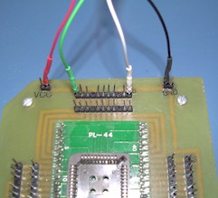 |
The motor has two sets of wires. The first set consists of two wires, one black and the other orange, both with exposed wire at the ends. You will NOT be using this pair for this lab!!! The other set of four wires are encased in a grey sheathing. These four wires will be connected to your ALTERA board. The red wire is power (5V) and should be connected to the VCC pin. The black wire is ground and should be connected to the GND pin. The green wire is the A-channel (CH_A) of your motor's optical quadrature encode and should be connected to pin 6 of your board. The white wire is the B-channel (CH_B) of your motor's optical encoder and should be connected to pin 40 of your board. |
Oct. 2000
Copyright © 2000, New Mexico Tech