The previous lab addressed the design of a quadrature position decoder, this lab involves the construction of a circuit to determine the signed speed, in revolutions per minute, of the rotating drive-shaft on a DC motor.
The design which you completed in lab 12 should serve as a starting point for this week's lab. The slotted disk on the motor shaft has 500 slots and you should expect four input transitions per slot resulting in 2000 input transitions per rotation of the motor's shaft. Furthermore, the motor has a 5.9:1 ratio gearbox which results in 5.9 rotations of the motor shaft for each rotation of the output drive-shaft thus giving 11,800 input transitions per output drive-shaft rotation. It is reasonable to assume that over a "short" period of time (say <1/100 sec.) the motor's speed remains constant due in part to the inertia of the physical device. One possible approach to determining the motor's speed would be to count the number of input transitions per unit time by resetting a counter at regular time intervals (i.e. speed=angle/time).
- If the motor speed was held constant at 1 rpm how many input transitions per second would you expect to see?
- Conversely, how often should you reset your counter such that 1 count per reset time-interval = 1 rpm?
Design a state machine which can determine the signed speed of your motor where rotation in the clockwise direction should give a positive speed. Note that you should only update the measured speed on the output of your design once per reset time-interval and not show intermediate counting values (latch the values?). You may assume that the motor has a maximum speed of 1000 rpm. How many bits will you use to represent the motor's speed?
Simulate your design and print a copy of the waveform(s) including all relevant signals.
DO NOT TURN ON THE POWER until a TA or instructor has checked your wiring.
|
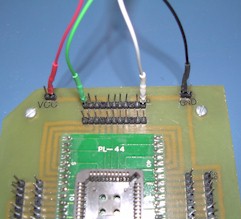
The motor has two sets of wires. The first set consists of two wires, one black and the other orange, both with exposed wire at the ends. Connect the black wire to the GND post and the orange wire to the 5-15V post on the top right-hand-side of your protoboard. These are the main motor power leads. The other set of four wires are encased in a grey sheathing. These four wires will be connected to your ALTERA board. The red wire is power (5V) and should be connected to the VCC pin. The black wire is ground and should be connected to the GND pin. The green wire is the A-channel (CH_A) of your motor's optical quadrature encode and should be connected to pin 6 of your board. The white wire is the B-channel (CH_B)of your motor's optical encoder and should be connected to pin 40 of your board. |
| Voltage | speed | Voltage | Speed | |
| 5 | -5 | |||
| 6 | -6 | |||
| 7 | -7 | |||
| 8 | -8 | |||
| 9 | -9 | |||
| 10 | -10 | |||
| 11 | -11 | |||
| 12 | -12 | |||
| 13 | -13 | |||
| 14 | -14 | |||
| 15 | -15 |
Oct. 2000
Copyright © 2000, New Mexico Tech