EE 212 Lab 4: Operational Amplifiers --- Part I
The purpose of this lab is to examine basic DC amplifier configurations of an op-amp.
Make all measurements carefully. Measurements should be repeatable and accurate to 5 %. If you can't obtain this, ask for help. Adjust the scope for high accuracy --- the amplitude of a sine wave that takes up the full display can be measured much more accurately than one that is 1 cm high. When asked if measurements agree with what is expected, do the necessary calculations. Some calculations can be done before lab. Feel free to bring and use your book.
Inverting Amplifiers
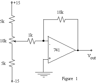
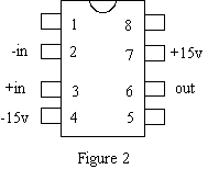
1. Construct an inverting amplifier having an input resistance of 1 kohm and a gain of -10 (Figure 1). Use the 741 op-amp with plus and minus 15 Volt supply voltages. Employ good breadboard technique by using the bus lines on your breadboard for each of the supply voltages and ground. See Figure 2 for the 741 pin connections for the op-amp package. Label the pin numbers on your circuit diagram. Vary the d. c. level of the op-amp input to confirm that the amplifier is operational.


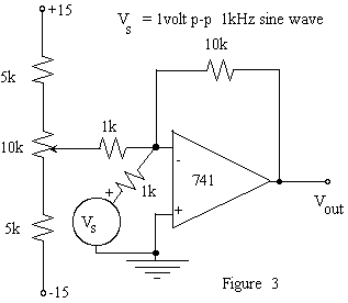
Add a 1 kHz sine wave to the amplifier input as shown in figure 3.
a) Measure the gain for several input amplitudes and compare with the theoretical gain.
b) Confirm that the op-amp inverts the input by displaying both input and output sine waves on the scope (sketch waveforms).
c) Vary the d.c. level of the input to confirm that the amplifier sums the two inputs.
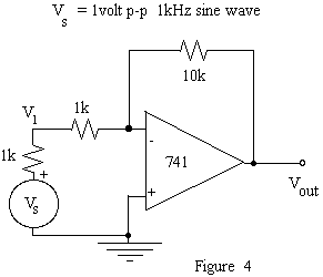
2. Remove the d.c. input (apply 1kHz input only). Measure the amplifier's input impedance, at
1 kHz, by putting 1 kohm resistor in series with the input (Figure 4). (Question: Why use this size of resistor -- why not a larger or smaller value?) The fractional change in the output will indicate how much V1 has changed. Make sure VS is still 1 volt. Measure (or try to) the output impedance by putting a 1 kohm resistor from the output to ground. (Question: Why use this size of resistor -- why not a larger or smaller value?) How much does the output voltage change? The change in the output can be thought of as voltage divider between Rout and the 1kohm resistor.
3. Increase the input amplitude to determine the voltage levels at which the output `saturates'. How do these voltages compare to the supply voltages?
Non-Inverting Amplifier
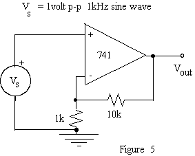
4. Wire up the non-inverting amplifier in Figure 5. What is the voltage gain? (Note -- it's not the same as the last circuit.)
5. Measure its input impedance, at 1 kHz, by putting 100kohm, or 1Mohm, resistor in series with the input. (Question: Why use this size of resistor - why not a larger or smaller value?) Does this configuration maintain the low output impedance you measured for the inverting amplified?
Follower
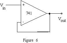
6. Build a follower with a 741 op-amp (Figure 6). Check out its performance; in particular, measure (if possible) Zin and Zout.
