EE 231
Homework Assignment 10
Due Nov. 5, 2008
- Design a synchronous sequential circuit to control the operation of a
vending machine. The vending machine sells a cup of coffee for 15 cents. It
has two input slots, one which will take dimes and the other which will take
nickels. There are two outputs -- one to dispense the cup of coffee, and the
second to give a nickel in change if 20 cents is inserted. If 15 cents is
inserted (one dime and one nickel in any order, or three nickels), the
dispense output should go high, and the change output should stay low. If 20
cents is inserted (two dimes, or two nickels followed by a dime), both the
dispense output and the change output should go high. Design this as a Moore
machine.
- Draw a state diagram for the circuit.
- Draw a state transition table for the circuit.
- How many flip-flops are needed?
- Derive equations for the next state, assuming use of D flip-flops.
- Write a Verilog program to implement the circuit.
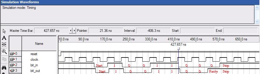
- Design a synchronous sequential circuit to generate a serial even parity
bit. The system has one input and one output. While no data is coming in,
the input is high. The input will go low (called a start bit) before the
real data comes. The start bit will be followed by seven data bits, then
another low bit (space for the parity bit), then a high bit (the stop bit).
Your circuit should put out the same sequence of data, except it should fill
in the parity bit. The parity bit should be a 0 if the seven data bits has an
even number of ones, and it should be a 1 if the seven data bits has an odd
number of ones. After transmitting the final bit, it should go back to the
state where it is waiting for another data word to come in. It is probably
easier to design this as a Mealy machine. Here is an example of the input and
output from the system. The input was 10011000, which has an odd number of
ones, so the system inserted another one into the eighth bit.
- Draw a state diagrm for the circuit
- From the state diagram, write a Verilog program to implement the circuit.
Bill Rison,
<rison@ee.nmt.edu >