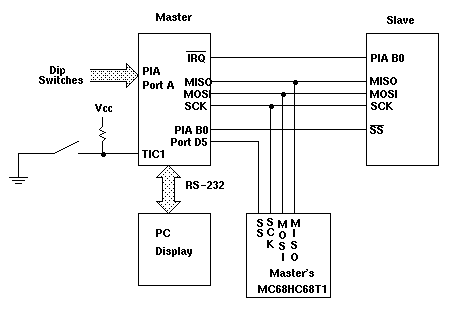
Figure 1: Connection of two HC11 EVBU boards for serial communication.
- Program the master's Real Time Clock with the correct time.
- When the switch is pressed, the falling edge should generate a
Timer Input Capture 1 interrupt. In the interrupt service routine, the master
will read the dip switches connected to its PIA Port A, send that number to the
slave over its SPI, then return from the interrupt service
routine.
- When the slave brings the master's IRQ line low, the master will enter an IRQ interrupt service routine. In that routine, the master will read the value of the register from the slave and the time from the Real Time Clock, and display the time and the value of the slave's register on the PC's display.
- An interrupt will be generated when the slave receives data on its SPI.
In the interrupt service routine, the slave should read the value from the SPI
and find the contents of the appropriate internal register. It should write
that data to its SPI data register, then bring Bit 0 of PIA Port B low to
tell the master it has its data ready. It should wait until the master reads
the data in the SPI, then bring Bit 0 of PIA Port B high, and return from the
interrupt service routine.
- The time from the falling edge on TIC1 to data being sent over the
SPI. This is how long it takes the master to get into the TIC1
interrupt service routine, read Port E, and send the data.
- The SPI clock frequency.
- Verify that the data on the SPI is valid on the falling edge of
SCLK, and the the data is sent with the most significant bit first.