Lab 4: DIODES AND ZENER DIODES
The purpose of this laboratory is to investigate the i-v characteristics of diodes.
The i-v Characteristics of Diodes
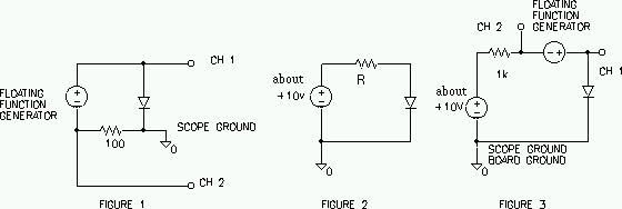
Use the circuit in Figure 1 to sense the i-v characteristic of the 1N4001 rectifier diode, and display the characteristic on your scope using its x-y capability. This is very similar to the method we used to measure the transfer function in lab 1. Note that the signal generator must float in this circuit. Many instruments receive their ground reference through the power cord (our scope, power supply, and signal generator) to prevent dangerous shock. By using the isolation transformer you may break this reference and set a new reference by the output connections.
1. Change your scope inputs/settings to obtain a `normal-looking' i-v characteristic (e.g. Sedra and Smith p. 125). The diode can handle 50 V reverse voltage and 1 A forward current. Vary the amplitude of the signal generator and observe the x-y trace. What maximum values of forward current and reverse voltage are you able to obtain with your signal generator? Are you close to the diode maximums? At what voltage (within 0.1 V) does the diode appear to `turn on' (current starts to flow)?

2. Copy or sketch the i-v characteristic when the peak forward current
is 20 mA. Label axes and add voltage and current scales. Measure the
forward voltage at 1 mA and 10 mA (use the time mode and cursors).
Does the forward characteristic
remain exponential up to the maximum forward current? (Can you tell?)
3. Remove the diode from the circuit and use the diode setting of your multi-meter to check the diode. In this setting the multi-meter puts 1 mA into your diode and measures the voltage, This multi-meter setting is similar to the OHM setting.
Zener Diodes
4. Display and copy the i-v characteristics for the 1N5229 and 1N5237 zener diodes. For each diode, measure the zener voltage at a reverse current of 20 mA and compare with the specification values (4.3 V for 1N5229, 8.2 V for 1N5237). Which diode has the steeper slope in the breakdown region? Which would make a better voltage regulator?
5. Each of the zener diodes has a 500 mW power rating. What maximum steady zener current does this imply?
Diode Forward Characteristics
6. Compute the parameters n and Is which govern the forward diode characteristic by measuring ID, vD at two points in the forward bias region of your 1N4001 diode (use ID = 1 mA, then 10 mA). Use the circuit shown in Figure 2 (you are not using the function generator or scope this time). Adjust the 15 V power until the voltage accross the resistor is 10V, and measure the diode voltage. Make measurements for the 10 K and then for the 1 K current limiting resistor. Do this accurately using a digital multi-meter (find the current from a voltage measurement). Sketch circuit and show calculations for n and Is (Ref: Sedra and Smith p. 132-134).
Compare the 1 mA voltages of parts 2, 3 and 6. If the difference is more than 20% repeat and carefully check each measurements.
EXTRA CREDIT.
7. Measure the incremental resistance rd of the above diode at d.c. bias current ID = 1 mA (see figure 3.25 in Sedra and Smith). Use the circuit in Figure 3 and your oscilloscope. (The floating signal generator provides a "small signal" vd, id around the bias point set by the dc power supply. Observe the small signals using AC coupling on the scope.) The incremental resistance is given by rd = vd / id. Compare your measurements with the theoretical value for rd (Eq 3.53 in Sedra and Smith).