Lab 7: DIFFERENTIAL AND INSTRUMENTATION AMPLIFIERS
In this lab we will experiment with differential amplifiers and use a so-called `instrumentation amplifier' to measure the output of a strain gauge. The instrumentation amplifier is a high-gain high-input-impedance high-CMRR differential amplifier.
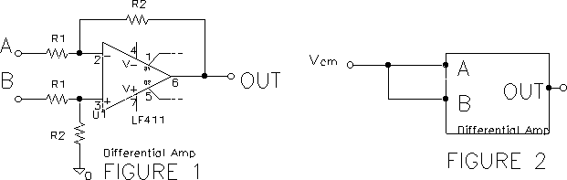
Differential Amplifiers
A. Construct the following differential amplifier (figure 1) with R1 between 4 and 6 k and the difference of Va and Vb amplified by about 30. Build it in the center of your protoboard to leave plenty of room for later additions.
1. Connect b to ground and a to the signal generator, and check that the gain is about 30. With the difference signal set to zero (as shown in the common-mode test circuit, figure 2) test that the circuit attenuates or rejects a common-mode input signal Vcm , and measure the `gain' of the amplifier for a common mode signal. Use a common mode input Vcm = 10 V p-p at 100 Hz. Why is the output not zero?
2. Improve the common mode rejection by replacing part of R2 in the non-inverting leg with a potentiometer (with the pot set to the middle of its range, the total resistance replacing R2 should be equal to R2). Adjust to maximize the common mode rejection; compute the new common mode gain. Sketch circuit. Why has the common mode rejection been improved?
3. The `Common Mode Rejection Ratio' (CMRR) is defined as the ratio of the signal gain to the common mode gain. Compute the CMRR of the above circuit.
B. Instrumentation Amplifier
4. Convert your differential amplifier to the classical `instrumentation amplifier' shown (figure 3) by adding a non-inverting amplifier to each input. Use 411 op amps for each of the non-inverting stages. Lay the circuit out neatly. Select the resistance values to give the amplifier an overall gain of about 600 to a differential input signal. Sketch circuit and test its operation by checking that all levels = 0 when the inputs are grounded (adjust R5 so the output is less than a volt). Check to see that a common mode input is rejected (figure 2). Check to see that the gain is near 600. (If the circuit does not pass these tests, revert to trouble-shooting mode.)
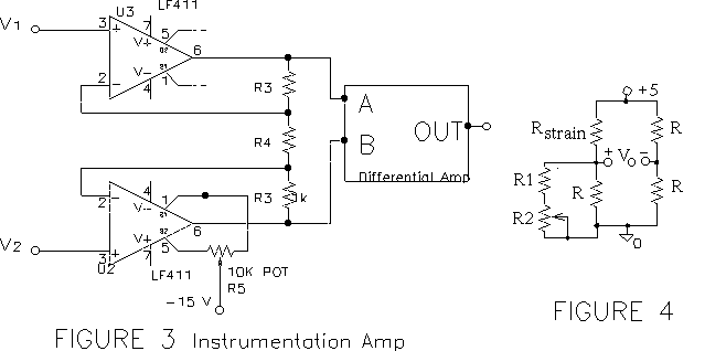
5. The resistance of a strain gauge changes by a few tenths of an ohm as it is stretched or compressed. The Wheatstone bridge is used to convert the small change in resistance to a small voltage.
Since we have only one strain gauge, the lab instructor will supply the gauge and bridge.