In this lab we will In this lab we will investigate a bipolar junction transistor (BJT) amplifier and emitter follower.
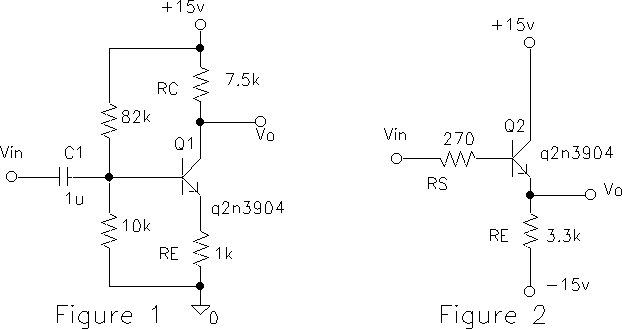
The amplifier circuit of last week's lab is impractical because the bias or operating point depends on the beta of the transistor. The following bias technique controls the voltage across RE and hence the emitter current IE (Example 4.7).
1. Construct the circuit in Figure 1 and measure the d.c. bias voltages at the base, emitter and collector. From your measurements, determine VBE, VBC. Is the transistor biased in its active mode? What are the d.c. (Q `quiescent') values of IC, IE?
2) Apply a triangle wave to the input and measure the voltage gain. Is the gain close to that found in the prelab?
3) The voltage gain can be increased by decreasing RE. Reduce RE to zero for signal frequencies by `bypassing' it with a large capacitor (100 uF) in parallel with RE. (Be sure to observe the correct polarity of the electrolytic capacitor.) Reduce the input amplitude and look at the output waveform.
Further reduce the input amplitude until the output is approximately linear and measure the gain. The gain has been increased to the large values, but at what expense?
The Emitter Follower Amplifier
4) When the input signal is applied to the base and the output is taken at the emitter, Figuure 2, the amplifier is called an `emitter follower'. This is because the emitter voltage `follows' the base voltage. Emitter follower amplifiers are useful because they have a high input impedance and a low output impedance. They amplify the signal power by increasing its current, and are therefore sometimes called a `current booster'.
Construct the circuit in Figure 2.
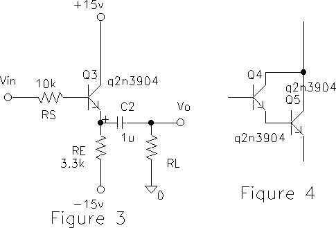
Sketch an equivalent circuit for the amplifier output and compute
Zout from your measurement. Compare with the theoretical value
Zout = [re + RS /( beta + 1)] || RE.
How much output voltage would you have gotten by connecting RL
directly to the source (RS is part of the source)? What does
this show?
7) EXTRA CREDIT. In the emitter follower (Figure 3) replace the transistor by two transistors connected in a Darlington configuration, (Figure 4): What is the effective beta of this `super beta' transistor? Measure Zin and Zout of the follower now?