EE322 Laboratory
Noise
In this lab we will measure the noise due to resistors and other components.
Resistor and Op-amp noise
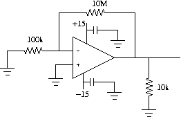
- Build an inverting amplifier with a gain of 100 using a LF411.
Use a 10M resistor as the feedback resistor. Ground the input. Add a 10k resistor
to the output as a load. Add 0.1 uF capacitors from each power connection to ground
at the LF411.
- If there is 60 Hz interference on any of these measurements, the effect on the measurement
can be removed by triggering on the ac-line, setting the time resolution at 0.1 ms/div, and
offsetting the time so that the resulting noise waveform is flat.
- Build the circuits neatly to reduce the chance of oscillations. If there are
oscillation make sure you have the power supply bypass capacitors, all grounds are
connected in the same place, and the wires are short.
- Look at the output with a 1X probe. At 1ms/div the output should be a random
noise signal. Record the peak-peak signal level.
- Change the input and feedback so that feedback resistor is 100k and the gain is sill 100.
What is the new output noise voltage. By what factor did it change? What factor
does the theory predict?
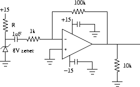
- Instead of grounding the positive input of the op-amp connect it through a 1M to ground.
Measure the peak-peak noise voltage.
- Repeat this 3 more times changing the resistor from the positive to ground to 10k, 100k, and 10M.
- Plot the measured calculated and pspice noise values versus resistance.
Avalanche noise
- Reconnect the positive terminal to ground. Connect the input through a 1.0 uF non-electrolytic
capacitor to reversed biased 8 V zener. The amount of noise will depend on the current through
the zener. Measure the noise with the following resistors between the zener and 15 V:
1k, 10k, 100k, and 1M. Plot the measured noise versus zener current.