1)Open
PSpice (MicroSim DesignLab Schematics) - Figure 1
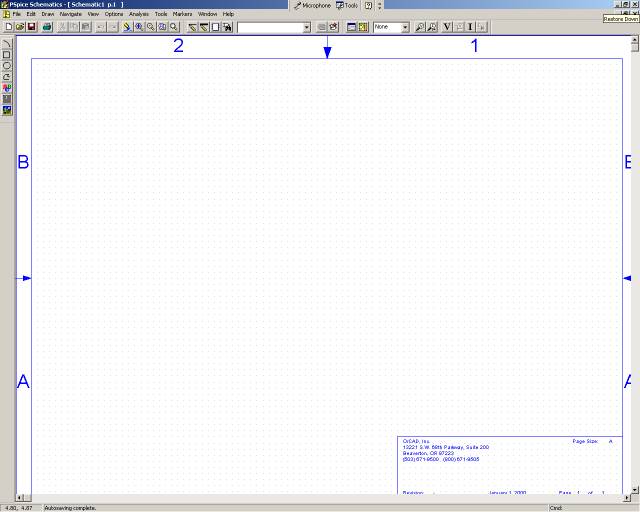
Figure 1
2)Click
on Draw -> Place Part (Crtl-P) or the binocular icon
3)Place
2-Q2N3906, 2-r,1-VDC, and 1-GND_EARTH and click close (to find each part
just type it in the name and click place, click on the schematics however
many times you need that part) - Figure 2
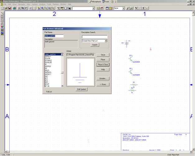
Figure 2
4)Rotate
transistors, and resistors to match schematic on page 88.
a.You
can use Ctrl - R to rotate and Ctrl - F to flip
5)The
load resistor is just a normal resistor and will deal with how to set it
up in a minute.
6)Align
all parts as in Figure 2.45 and connect wires as shown (You can zoom in
to make the circuit easier to work with)-
Figure 3
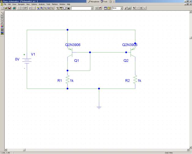
Figure 3
7)Change
the value of R1 to 14.4K by clicking on the value, and the value of the
VDC to 15 volts
8)Instead
of using a variable resistor we will allow PSpice to simulate the variable
resistor for us, click on the value of R2 and change it to be ?{RLoad}?
(The curly braces are very important) - Figure 4
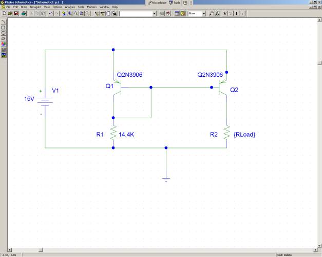
Figure 4
9)Open
the parts lists once again and add the part ?param?
10)Double
click on the part, a dialog box will open up
11)Change
?Name 1? to have the value of RLoad, and ?Value 1? to have a value of 1K
- Figure 5
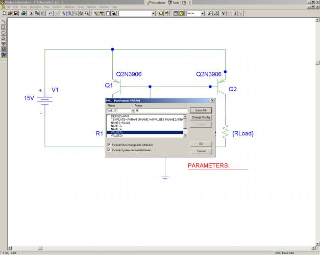
Figure 5
12)Click
Save Attr, and click OK.There now
should be RLoad 1K underneath Parameters
13)We
now need to set up the DC Sweep, click on Analysis -> Setup, a menu will
show up, check DC sweep and click on the button.
14)Change
the values to the following - Figure 6
a.Sweep
Variable type - Global Paramater
b.Name
- Rload
c.Start
Value, End Value, Increment - 1, 100k, 1k
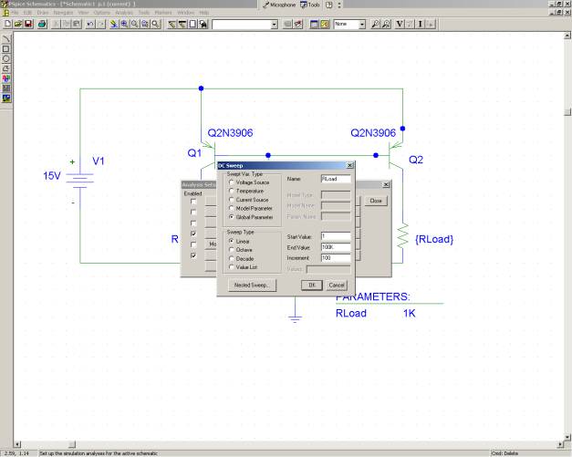
Figure 6
15)A
current marker must also be added right before (or after) R2(RLoad)
16)The
simulation may now be run by Analysis -> Simulate (or F11) - Figure 7
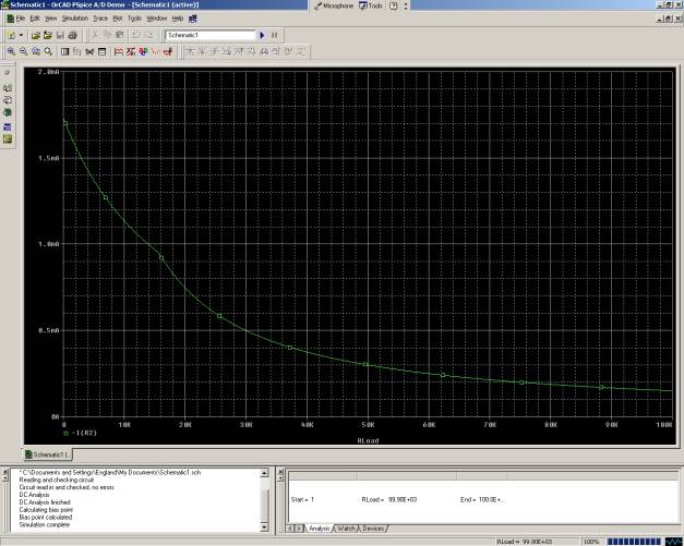
Figure 7
17)You
will notice that the current breaks at about 16K, edit the DC sweep parameters
to narrow in on this spot and re run the simulation.You
may want to add a voltage marker to see what the voltage is doing at the
same time.
Questions:
1)Is
this a good current mirror?Why or
Why not?
2)Why
does the current mirror break down at this value of the load?