EE101 - Lab 3: Introduction to PSPICE/Multisim
Prelab Exercises
-
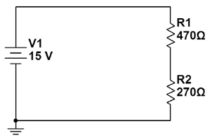
Analyze the circuit below.
-
Label each node in the circuit. (there are three, including ground)
-
Determine the Req for the resistors in the circuit.
-
Find the source current through the circuit.
-
Find the voltage at each node. (that is, the voltage drop
between that node and gound).
-
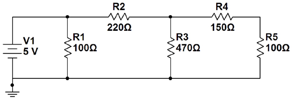
For the circuit below:
-
Starting at the left and moving to the right across the circuit shown below,
label nodes 1, 2 and 3 in the circuit. (The ground plane will be node 0).
-
Using any methods we have covered to date in class, determine
the voltage drops across each resistor and all the indicated currents.
-
Perform a power balance as a means of checking your work.
-
Determine the all of the node voltages in the circuit. These are the voltage drops between each node and the reference node (node 0, which should be ground).
(end of pre-lab)
Lab Exercise 3: Introduction to PSPICE/Multisim
In this lab you will learn how to use a software application to analyze resistive networks
containing a DC voltage source. A classic industry-standard program used for this purpose (and many others) is called PSPICE, or 'spice.' A number of software suites apply the spice model to circuit analysis. The specific software we will use is called Multisim. While Multisim is a branded application that is similar to (and actually uses) the spice model, we will use the Pspice name as a generic term for our circuit analysis software, interchangably with the brand name Multisim.
Getting started with the lab computers:
-
Log on to a computer (click the'user' login button). Log in to the EE network (the black screen that asks for your username and password). If this screen doesn't come up automatically or if you close it accidentally, go to the start menu and look for "connect to network." In order to protect the privacy of your password, the characters will not display as you type them. If you have problems logging in, be sure you are using your proper EE network user name and password (this is separate from whatever you may have established at the TCC).
-
It is a good idea to keep all of your
computer work for this class in a separate directory structure. "ee101"
would be a logical name for the parent directory, and each lab number for
the separate lab exercises. For example, you may wish to keep the work
for this lab in U:\ee101\lab3. If you are not familiar with navigating and creating directories in Windows
ask someone to assist you.
Getting started with Multisim:
-
Once you are logged in, to call up PSPICE, go down to the taskbar and click
on the Start button. Go to the All Programs menu
and select Applications then click on Multisim 11.0.
- Before you begin using the software, note that there is s great introduction in the Multisim help files. Go to the Help menu, select "Multisim Help" and familiarize yourself with the User Interface and Schematic Capture-Basics sections. More advanced info is also available here which would be a good idea to read through as we start to use this software more, especially in future labs.
- Another important note: As with most software, Multisim has an UNDO function (Ctrl-z), however it only remembers your last four actions!
- PART 1:
You will now enter and analyze the first prelab circuit (shown again below, as it will look in Muiltsim).
Creating a circuit diagram works much like a paint program. First you place components on the workspace, and then you connect them together by 'drawing' wires. Then we will simulate its behavior and attach virtual instruments to the circuit to observe various measurements.
- When Multisim opens, it automatically starts a new circuit file for you. The first thing you should do is save this into the directory you created earlier (on your network U drive, in the EE101/Lab3 folder). Name it appropriately for the first circuit in this lab (there will be another one later). Whenever creating a file as part of a lab experiment it would be a good idea to make a note of the file name and location so you can find it easily later... say, like, right here: _________________________. Also remember to save your work often as you go.
- Place components: Let's start with resistors. Multisim will name your resistors numerically in the order you place them, so it's a good idea to go in the order that they're labeled on your original circuit so you don't have to rename them later.
- Go to the Place menu and select Component. The Select a Component window will open. From here you can place any kind of component, resistors for now, and later we'll also place the voltage source and ground from this screen as well.
- In the Group window select Basic and then click on Resistor from the Family list below. You should see a schematic symbol for a resistor in the preview pane. Select the desired value from the list. You can filter the list by typing the value in the Component box, as you type it will filter based on the characters you enter (next time this window opens the list will still be filtered however, so you'll have to delete those characters to see other values again). Be sure to choose the resistor with the proper scalar (i.e. 100 vs. 100k vs. 100M, etc.). These values can also be changed after you place the component by double-clicking on the component in the workspace.
- Click on OK and the window will disappear. Instead of a normal cursor now your mouse has a resistor you can move around. If you want to rotate the resistor (before or after you place it) hit Ctrl-R. To place it on the workspace, click and release the left mouse button. It will place your resistor and automatically re-open the Select a Component window. Now you can select a new value for your next resistor and place it on your workspace. To close the window without placing another component click Close or hit the ESC key.
- Now we can place the voltage source. From the Select a Component window, under Group select Sources then the POWER_SOURCES family. Choose DC_POWER from the component list and a battery schematic symbol will apear in the preview pane. Click OK and place the source on your workspace.
- When the Select a Component window returns, now select Ground from the component list. Again, an appropriate schematic symbol will be shown. Click OK and place it. Hit ESC to cancel the placement window when it re-appears because we are done placing components for this circuit.
- Note that the default source voltage is 12v. Double-click voltage source on the work space to open the attributes window (you can do this for any component). In the Value tab you can set the DC voltage to whatever you need, in thic case 15v. You can use the Label tab to rename the component if you like, but there's probably no need in this case.
- Connect components: There are several ways to make 'wire' connections between components.
- You can click and drag a component until its lead touches the lead of another component you want it to connect to. A red dot appears to indicate that a connection will be made when you release the mouse button. Release the button and the components should be joined. You can now drag them apart and reposition as necessary, the connection will remain and re-draw itself accordingly.
- You can also draw wires manually between leads that you want to connect together, similar to drawing lines in a paint program. Simply hover over the end of a componentt lead and a dot and cross-hair will appear. Click and release once to begin the wire trace. Move the mouse to the lead you want to make a connection to (the dot turns red when you're at a place where it can make a connection), click and release the mouse button again, and the wire will be complete.
- Wires will automatically route themselves as you draw, and it may seem difficult to control the path. However, once placed, they can be selected and re-positioned as desired. You can also force a corner wherever you want while drawing a wire by clicking the mouse button once. Wires that intersect without a dot are not connected to each other. If you want to join intersecting wires together you need to click down on the intersection to create a junction as you pass over it and a dot will appear to confirm the connection.
- Completing the circuit design: When you are finished placing and connecting components there are a number of final steps before simulation.
- From the Tools menu, select Electrical Rules Check. Accept the defaults and click OK. A results pane will open at the bottom of the work area. A brief test report is displayed. Any errors or warnings will appear there. If there are errors or warnings, double click on that line in the report for more details. Fix any errors and keep troubleshooting and re-testing until you get a successful result without errors.
- This is a good time to look at the Netlist Report: From the Reports menu select Netlist Report.This is a table that summarizes the components and connections in your circuit. This is where you can learn how Multisim has labeled your nodes (which it calls 'nets'). Ostensibly there should be one net/node for each component connection in your circuit. Multisim will assume your wires are ideal so a wire connecting two components together will be treated as a single net. You will need to compare your initial schematic to the Netlist Report to convert between your node names and the names Multisim has assigned automatically. Note that Multisim probably numbered them differently. This is not a problem, you just need to be sure you keep track of which node is which when you refer to them.
Also note that each component has a pin number for each lead. For voltage drop reference, Multisim will calculate voltage drops from pin 1 to pin 2. This means that to follow the labeling system you're accustomed to, you need to treat pin 1 as the (+) polarity label and pin 2 as the (-) label. If your results indicate a positive voltage then pin one is at higher potential than pin 2. Converesly if you get a negative value it means that pin two is at higher potential than pin 1.
- Print your circuit and put it in your lab book (always do this from now on). Be sure to use the Print preview and Print options features in the File menu to optimize your printout before you send it to the printer.
- Simulating your circuit and making measurements:
DC Analysis: This is an automated circuit simulator feature that evaluates your cirucit and calculates the node voltages and source current for you. There are some parameters we need to control in the setup, then we'll simulate and look at the results.
- Be sure your file is saved.
- Simulation Setup:
- From the Simulate menu select Analyses: DC Operating Point. When the window opens, set the following parameters in the Output tab:
- Simulating Node Voltages: There are two main boxes. The Variables in circuit box on the left shows the nets in your circuit as possible simulation output data variables. The Selected vairables for analysis box on the right shows the list of outputs you have selected to include in the simulation which starts empty. You need to populate the Selected variables list with the outputs you would like it to generate results for.
For this circuit it probably shows I(V1), V1, and V2 as output options. In this case the I(V1) indicates that it will calculate the current through the source which is connected between ground and net number 1 (V1). The sign of the current value will use the voltage polarity as a reference since there is no current arrow indicator. Select each and add all three of them to the selected variables list using the Add button. You can select multiple items by holding Ctrl key while clicking on them. This tells Multisim that you want all three of those values calculated in the simulation.
- Simulating voltage drops that are not node voltages: The simulation above will only provide node voltages. We know that the voltage source and the 270 Ω resistor are connected between a net and ground so their voltage drops are already defined in the simulation. However, the 470 Ω resistor is connected between two non-reference nodes. Therefore in order to calculate its voltage drop we will have to subtract one node voltage from the other. As we learned with nodal analysis, the voltage drop across that resistor in the 'downward' direction will be the node voltage above it minus the node voltage below it. It happens that the DC analysis will calculate such mathematical functions for us...
In the DC Analysis window's Output tab, click the Add Expression button which will open an Analysis Expression window. Select the high-potential node from the Variables list (probably V1 but check the net list to confirm this) and click the Copy Variable to Expression button. Then type a "-" (minus sign) in the Expression box after V1. Now select the low-potential node (probably V2 but again check this on the net list first) and copy it to the expression. You can also just type all of this directly into the expression box if you prefer. This will ask Multisim to (in this case) calculate V1 - V2 and display it along with the other values so we can easily see the voltage drop across the 470 Ω resistor. Remember that yours may very well be reversed depending on how Multisim labeled your nodes so, as mentioned earlier, you MUST check the netlist report first to determine which node voltage is which!
- Click OK to get back to the DC Analysis window and click the Simulate button to generate your results. If you hit OK instead you can get back to the simulation screen again through the Simulate menu just as before, your settings will be retained.
- Simulation Results: When the simulation is complete a window will open on top of your workspace. This shows a table of values for each variable you defined, plus the voltage drop expression you created.
- As with any data you generate, you should copy this table into your lab book.
- Look over the data and correlate each value with the node voltages you labeled earlier and calculated in the prelab. Record this info on your lab book. (Hint: When you put this table into your book, add another column for theoretical values from the prelab, then perhaps an additional column for percent error from your comparison calculations in the next step).
- Compare your results for each with your prelab calculations using the familiar percent error equation.
- Note that the source current shows as a negative number. This is because for lack of current direction arrows, Multisim uses the polarity of the voltage source to indicate the current direction. Positive current readings are for when current is flowing from high to low potential as when flowing from + to - across a resistor. For a voltage source that is delivering energy, current flows from - to + with respect to the voltage source schematic symbol, and as such Multisim displays thecurrent as a negative value.
- Your voltages should all be positive. If the expression you created for the 470 Ω resistor gives you a negative value it means you subtracted in the wrong direction. Use the results table to double-check your conclusions about which node is which, fix your expression, and re-simulate.
- Print the results window and paste it into your lab book. Be sure to use the print preview and print setup features to optimize your printout before you sent it to the printer.
- PART 2: We will now work with the second circuit from the prelab, again shown below as it will look in Multisim.
- Close the circuit file from Part 1, open a new file, and save it under a new name (and of course make a note of it).
- Create the circuit from Exercise 2 of the pre-lab (shown above) in Multisim and simulate
the circuit using the same DC Analysis feature. You'll have to set up more expressions for this simulation as there are more voltage drops between non-reference nodes.
- Observe and record the same set of results and comparisons you made for the first circuit.
- With the information provided by the simulation (node
voltages and the source current), use KVL, KCL, and Ohm's Law to determine
all the voltages and currents associated with the circuit. Show all
your work in your lab write-up. Note that the prelab had you analyze this circuit using given theoretical data, here we will use the simulation data to make those calculations. As usual, in this step you'll have to look at the results and interpret the netlist it created to figure out how it labeled the nodes.
-
After you have completed all your calculations in the previous step, verify
that your answers are correct by comparing them to the lab instructor's
key or to your prelab. Fix any mistakes you have.
- PART 3: Questions
-
What are the advantages of using PSPICE to analyze a circuit? What are
the disadvantages?
- What is the difference between a node voltage and a component voltage drop?
September 2010
Copyright 2001, New Mexico Tech