- Turn on the oscilloscope with the button on the top. Attach a BNC to alligator cable to the Channel 1 BNC input connector.
- On the oscilloscope, set the following controls:
- Channel 1 Volts / Division = 2 (The CH 1 menu button enables/disables the channel, turn VOLTS/DIV knob).
- Time / Division = 250us (Turn SECONDS/DIV knob).
- Trigger Source = Channel 1 (Push TRIGGER MENU, select Channel 1 from the Source menu).
- Turn on the function generator. Attach another BNC to alligator cable to the output connector (be careful not to attach it to the Sync (TTL) output). Attach the red alligator clips from both cables together. Repeat with the black clips.
- You will now configure the function generator to output a 10Vpp (peak-to-peak), 1 Khz sinusoidal wave.
- Use the output arrows to select the sinusoidal wave pattern.
- Highlight the Frequency option (FREQ under Display/Modify) and use the MODIFIER and RANGE controls to set an output frequency of 1 Khz.
- Highlight the Amplitude option (AMPL) and adjust Vp (peak voltage) for 5 volts.
- You should now see a sinusoidal wave on the oscilloscope. If not, then ask a lab assistant for help. The problem may be with some oscilloscope settings, some "buried" function generator settings, or the physcial connection.
-
Now, make sure the sinusoidal wave is vertically centered on your scope.
- Press the Ch 1 menu button
- select the Ground option under the Coupling submenu.
- The Channel 1 vertical position should be set to 0.00 divs (0.00V). If it is not, adjust using the "Vertical Position" knob.
- Since the cosine wave is the standard for sinusoidal wave patterns, adjust the horizontal position of the wave so that the positive peak amplitude intercepts the vertical axis. This can be adjusted using the "Horizontal Position".
-
Using the cursors: The oscilloscopes are equipped with a set of horizontal and vertical
cursors to aid in obtaining measurements. You can use these to measure
various parameters like peak voltage, period, and frequency.
- Measure the Peak-to-Peak amplitude of the waveform using the horozontal cursors. To do this, press Cursor, and then select Voltage under the Type submenu. Use the Vertical Position knobs to place the cursors at Vp and -Vp. Under the delta submenu the peak to peak voltage will be recorded. Repeat this process to measure the Peak Voltage.
- Measure both the Period and Frequency of the waveform using the vertical cursors. To do this, press Cursor, and then select Time under the Type submenu. Use the Vertical Position knobs to again place the cursors. The delta submenu displays both the period and frequency measurements.
You should now have a stable cosine wave with an amplitude of 5 volts, a phase shift of 0 degrees, and a frequency of 1 Khz (see equation 1) display on the oscilloscope. Have a lab TA verify this.
v(t) = 5 cos(2 * pi * 1000t + 0) volts (1)
v(t) = 5 cos(62832t + 0) volts (2)
- What is the frequency of the waveform in hertz? What is the period? What is Vp?
- Adjust the function generator to output the waveform in equation 2. Start bringing up the frequency from 1 Khz to the value you calculated in part a, and notice what happens to the waveform displayed on the oscilloscope. Rreadjust the sec/div knob on the scope until one or two periods take up most of the the screen. What happens to the signal displayed on the scope as the frequency from the function generator gets higher?
- With the cursors, measure Vp (peak) and Vpp (peak-to-peak) and record these values in your lab book.
- With the cursors, measure the frequency of the waveform and record this value in your lab book.
- Sketch the waveform as best as you can in your lab book. Be sure to fully label your plot with axes, units and divisions.
- Build the circuit in Figure 1.
(Note: You do not have to use the protoboard's power supply for
this circuit. The function generator is providing the voltage source.
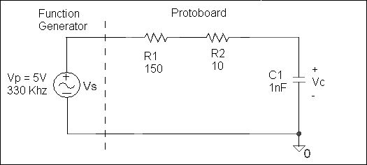
Figure 1.
- In this step we will connect a voltage source (the function generator) to your circuit, then measure Vs and Vc with oscilloscope probes. Essentially, Channel 1 will be measuring
the input of the circuit (Vs), and Channel 2 will be measuring the "output" (Vc). (You will need another BNC to alligator connector to use for measuring
on Channel 2 of the oscilloscope.)
- Connect the red and black leads from the function generator to the +Vs (red) and -Vs (black) connections on your circuit. This makes the function generator act as Vs.
- Connect the Channel 1 leads from the oscilloscope so that they will measure Vs. (Hook the red lead to the +Vs node in the circuit, and the black lead to -Vs.)
- Connect the Channel 2 leads from the oscilloscope so that they will measure Vc (Hook the red lead to the high potential node adjacent to the capacitor, and the black lead to the low potential node adjacent to the capacitor.)
- Note that all the black clips should now be connected to the same node in your circuit (ground). Two red leads are connected to the Vs node (function generator and channel 1), and one red lead is connected to the Vc node (channel 2).
- On your oscilloscope, display both the Vs and Vc signals simultaneously.
To do this, press the "Channel 2" menu to display the second channel (the
first should already be enabled). Also, set the ground reference (by vertically
centered both signals like part 1f).
-
Once the Vs and Vc waveforms are properly displayed, use the vertical cursors
to measure the frequency and period of each wave. Note that each
waveform has the same frequency and period.
- Using your input waveform as the reference, measure the time difference between it and the
output waveform. Be sure to adjust your volts and seconds per division to maximize the size of this diffence on the screen for more accurate measurements. This time delay is the tmax value that you have been introduced to in class. Convert this value to degrees using equation 3.
Phase shift theta: θ = -360 (tmax / T) (3)
- Use the voltage cursors to measure the amplitude your output signal. The output signal Vp should be smaller than the input Vp. Because this is in reference to the input voltage, figure out the ratio of output voltage to input voltage (Vc/Vs) and use it as a coefficient for Vs in your equation in the next step. This ratio is what we call "gain". Because the ratio is less than one (output is smaller than input) we call this kind of gain "attenuation".
- Write a sinusoidal equation for Vc based on the information you've gathered
in this section. Rather than using a constant value for Vp, specify it in terms of Vs using the ratio you found in the previous step. For example, if your output Vp was 3/4 of your input Vp, then your equation would look like Vc(t) = (3/4)Vs * Cos(ωt + θ). This is an explicit way to refer to the output relative to the input, and allows us to easily see the signal attenuation in the equation.
- Sketch and fully label (axis labels, tmax point, Vp, -Vp, and the period) the two waveforms in your lab book, on the same graph.
-
Once the Vs and Vc waveforms are properly displayed, use the vertical cursors
to measure the frequency and period of each wave. Note that each
waveform has the same frequency and period.
- Extra Credit (10%)
Before you dissemble your circuit, you can experiment with the input frequency to see how that impacts the "output".
- With the plots displayed on your scope, double the frequency to 660 KHz and measure the amplitude of your output waveform (Vc). Note that you'll have to adjust the seconds/division to view the new waveform.
- Increment your frequency again by 330 KHz and measure the output amplitude. Repeat this process until you have five or six frequency/voltage data sets
- Make a frequency response graph by plotting frequency on the horizontal axis and Vc on the vertical axis. Plot your Vc value at each tested frequency (including the orignal values from part C) and draw the curve that connects the points.
- Observe how the output voltage changes as frequency increases. What can you say about the response of this circuit? If it were a filter what would you call it?
- With the plots displayed on your scope, double the frequency to 660 KHz and measure the amplitude of your output waveform (Vc). Note that you'll have to adjust the seconds/division to view the new waveform.
Questions
- Is there a difference between peak to peak voltage and peak voltage? Explain your answer.
- If a waveform has a period of 10 ms, what is its frequency? If a waveform has a frequency of 25 KHz, what is its period?
- Describe the relative position the cursors should be in if you wanted to measure the peak voltage of a period sinusoid. Describe their position if you wanted to measure the period of the waveform. Describe their position if you wanted to measure the peak-to-peak voltage of the waveform.
September 2006
Copyright 2006, New Mexico Tech