In this lab step responses of RC and RLC circuits will be generated and studied.
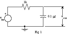
1. Construct the circuit shown in figure 1.

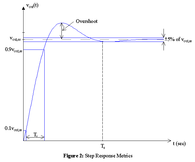
| Predicted | Measured | |
| Initial Value, vout(0) | ||
| Final (steady-state) Value, vout,ss = vout(¥) | ||
| 10% - 90% Rise Time, Tr | ||
| (Within 5%) Settling Time, Ts | ||
| Percent Overshoot, 100%(peak value - vout,ss) / vout,ss | ||
| Time Constant, t |

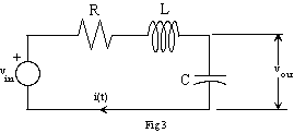
2. Determine values of R, L, and C for the circuit
shown in figure 3 so that
the step response is a damped sinusoid with an exponential decay governed by a s
of 105 (i.e. the damped sinusoidal
response goes to e-1 of its final value in 10 m-seconds)
and a frequency of 1MHz.
Use the value of L in your parts kit, i.e., 0.47mH or 0.68mH.

| Predicted | Measured | |
| Initial Value | ||
| Final Value | ||
| Rise Time | ||
| Settling Time (within 5%) | ||
| Percent Overshoot | ||
| s | ||
| w |
© Copyright 2003 New Mexico Institute of Mining and Technology