EE 212 Lab
Lab 1: Resistors and the Multimeter
Part 1: Current, I vs. Voltage, V for a Resistor.
Using a 22kohm resistor, verify that Ohm's law is obeyed by measuring
I and V for a few voltages, as follows
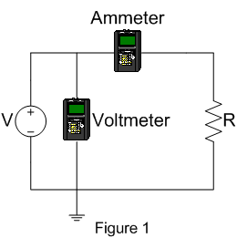
- Use the adjustable 1.3-20 V dc supply and construct the
circuit shown in figure 1 on your protoboard.
- Use two multimeters connected as shown to make the
measurements. (Note that voltages are measured between points in the
circuit, while currents are measured through a part of a circuit.
Therefore you usually have to break the circuit to measure a current.)
Be sure to use both positive and negative values of V.

MAKE SURE YOU DOUBLE CHECK YOUR CONNECTIONS BEFORE YOUR TURN ON THE POWER SUPPLY. IF YOU PLACE AN AMMETER BY MISTAKE ACROSS THE POWER SUPPLY YOU WILL BLOW OUT A FUSE.
Do the following
- Take at least ten measurements and plot the results.
- From the plot determine the value of the resistance, does it agree with
what is marked on the resistor.
- Compare to the values marked on the resistor to values
measured with your multimeter.
- Comment on the accuracy of your instruments and whether your
measurements agree with theory.
- The voltmeter is not measuring the voltage at the place you
want, namely across the resistor. Does that matter? How can you fix
the circuit so the voltmeter measures what you want?
- Describe the impact of the voltmeter and ammeter internal
resistances on the accuracy of the above measurements. For the
instruments you are using, which connection is best?
Part 2: I vs V for a Lamp
Now perform the same measurements for a lamp keeping the voltage
under 10V to protect the lamp from damage.
- Plot the results.
- What is the "resistance" of the lamp?
- What is the difference between the voltage-current relationship
of the resistor and lamp?
- Why are they different?
Part 3: Thevenin Equivalent Circuit
Construct the voltage divider shown in the left portion of figure
2. Apply Vin = 15V and leave the 10kohm load resistor off for now.

- Measure the (open circuit) output voltage across the load connection nodes.
- Measure the short circuit current.
With this information, determine the Thevenin equivalent circuit. Next,
- Attach the 10kohm load resistor to the output.
- Measure the voltage across this load.
- Calculate the expected output voltage using the Thevenin
equivalent circuit and compare it to the measured value.
- Keep the circuit you just built. Now build the Thevenin equivalent
circuit shown in the right hand portion of figure 2 (without 10kohm
load resistor) using the variable power supply and a
resistor close to the required value. Check to see that its Thevenin
voltage and Norton current are correct. Then attach the same 10kohm
load resistor used above to see if the Thevenin equivalent circuit
behaves the same as the original circuit.
- With the original voltage divider (left portion of figure
2), replace the 10kohm load resistor with a 10kohm potentiometer
(pot). Adjust the pot to achieve 3V across it and record the pot's
resistance used to achieve the 3V (use the ohm meter function on
the multimeter). Compare this resistance to the value calculated
from the Thevenin equivalent circuit where 3V is assumed across an
unknown load resistor.
© Copyright 2008 New Mexico Institute of Mining and Technology


