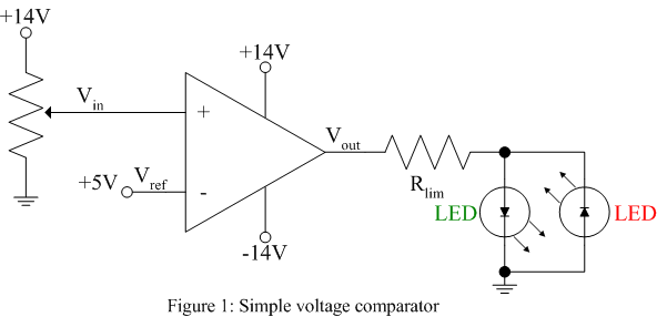
The purpose of this lab is to build simple voltage comparators that signal when an input voltage is greater than or less than a reference value. These comparators are constructed from op-amps without external negative feedback such that they saturate near their positive or negative supply voltages depending upon the difference between the inverting and non-inverting input voltages.
The comparator circuits shown below produce a positive output voltage when the input voltage is greater than a reference voltage and a negative output voltage when the input voltage is less than a reference voltage. These positive and negative output voltages are used to drive green and red light emitting diodes (LEDs) to signal the result of the comparison.
1. Build the following circuit using a 356 or 741 op-amp, a one turn pot to vary the input voltage around 5V and the resistor value for Rlim determined in the prelab. Use a green LED to signal an input voltage greater than the reference and a red LED to signal an input voltage less than the reference voltage.
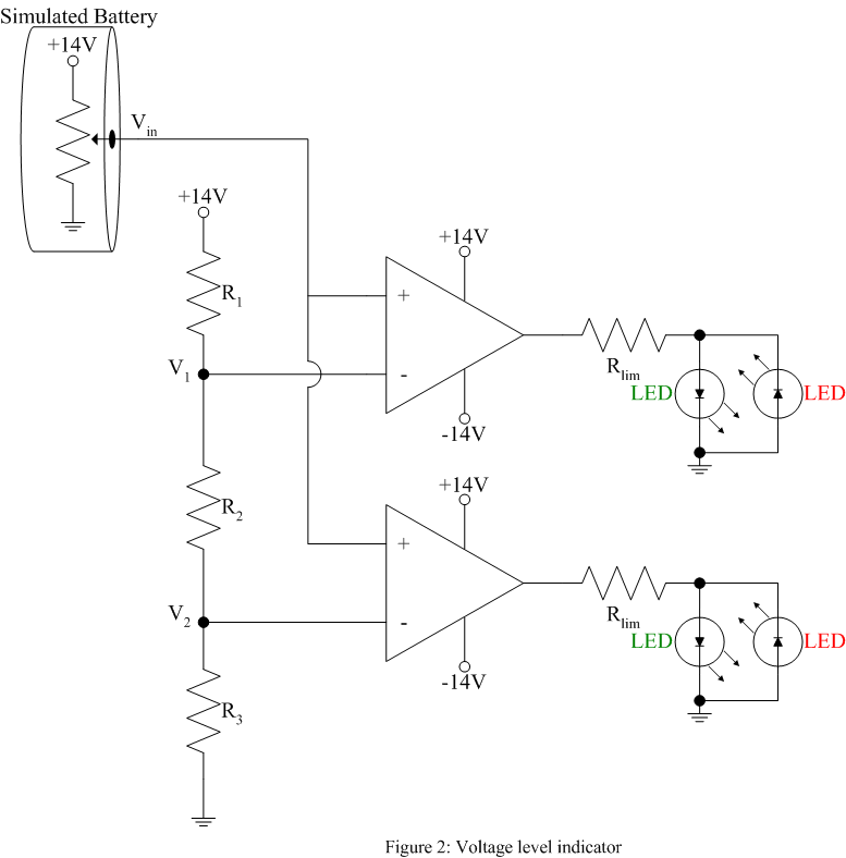
2. A two-stage 12V battery voltage monitor as shown in figure 2 can be constructed using the op-amp comparator. Find values of R1, R2, and R3 such that the reference voltages are set to V1 = 11V and V2 = 10V noting the high input impedance of the op-amp will have little effect on the resistor chain. Use a pot to vary the input voltage simulating a discharging battery. In the beginning (battery voltage > 11V) the LEDs should read green-green. When the voltage is between 10V and 11V the LEDs should read red-green and when the voltage falls below 10V the LEDs should read red-red.
Note: The op-amp switching time from one rail to the other can be reduced by choosing an op-amp with a higher slew rate and by placing diodes around the op-amp such that the op-amp never enters saturation.