EE 212L: Comparators
Objective: The purpose of this lab is to build simple voltage comparators that signal when an input voltage is greater than or less than a reference value. These comparators are constructed from op-amps without negative feedback such that they saturate near their positive or negative supply voltages depending upon the difference between the voltages applied at the inverting and non-inverting inputs.
Pre-lab:
- Recall the operating equation for an op-amp is vout = A(v+ - v-) where vout is the output voltage, v+ is the voltage at the non-inverting input, and v- is the voltage at the inverting input. What is the rated (large signal voltage) gain A of the LM741 and LF356 op-amps in V/V?
- Given the op-amp gain A, what would one expect vout to be if v+ > v- (taking saturation into account)?
- What would one expect vout to be if v+ < v- (taking saturation into account)?
- A typical LED allows current to flow in only one direction (from
anode to cathode - see Figure 1 below), has a voltage drop of around
2V when forward biased, and requires approximately 10mA of forward
bias current to emit light (less current and it will be dim, more
current risks damage). Consider the op-amp circuit of Figure 2 in
the lab. If the output of the op-amp is saturated near either its
positive supply voltage (+15V) or negative supply voltage (-15V),
what resistor value should be chosen for Rlim such that
the current through the LED is near 10mA? Hint: does
Rlim = (14V - 2V)/10mA make sense?. Note the +-14V
output voltage swing is given in the op-amp's data sheet when supply
voltages of +-15V are used.
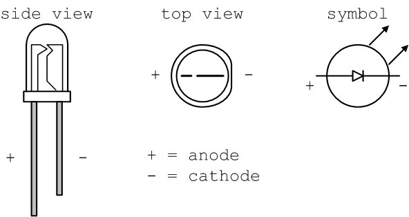
Figure 1: LED diagrams
- When vin = v+ > v- = vref in Figure 2, which LED (red or green) would you expect to be on?
- When vin = v+ < v- = vref in Figure 2, which LED (red or green) would you expect to be on?
- Determine the resistor values (R1, R2, R3, Rp) needed for part two of the lab based upon the criteria given there and Figure 3.
Laboratory Procedure: The comparator circuits shown below produce a positive output voltage when the input voltage is greater than a reference voltage and a negative output voltage when the input voltage is less than a reference voltage. These positive and negative output voltages are used to drive green and red light emitting diodes (LEDs) to signal the result of the comparison.
- Build the circuit shown in Figure 2 using a 356 or 741 op-amp, a
one turn pot to vary the input voltage vin around 5V, 5V
for the reference voltage vref, and a resistor value for
Rlim near that determined in the prelab. Use a green LED
to signal an input voltage greater than the reference and a red LED
to signal an input voltage less than the reference voltage.
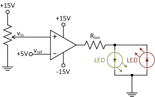
Figure 2: Op-amp-based voltage comparator
- A realistic scenerio is the need to monitor a battery's voltage
and display its state. A two-stage 15V battery voltage monitor
as shown in Figure 3 can be constructed using the concept of the
op-amp comparator discussed above and shown in Figure 2.
- Consider the circuit shown in Figure 3, and find values of R1, R2, and R3 such that the reference voltages are set to v1 = 14V and v2 = 13V noting the high input impedance of the op-amp will have little effect on the resistor chain.
- A one-turn potentiometer (here in the simulated battery) can be difficult to tune to desired values of resistance, and correspondingly voltage. Therefore, a resistor is often placed series with it such that the combined resistor and potentiometer can more easily be "tuned" to desired values. Assuming a 10kΩ potentiometer is used in the simulated battery, find a value for the resistor Rp in series such that the intermediate voltage vp = 12V when 15V is connected to the top of the potentiometer as shown in Figure 3.
- Build the circuit in Figure 3 using the simulated battery's voltage as the input vin to the comparators.
-
Use the potentiometer to vary the input voltage simulating a
discharging battery. In the beginning (battery voltage > 14V)
the LEDs should read green-green. When the voltage is between
13V and 14V the LEDs should read red-green and when the voltage
falls below 13V the LEDs should read red-red.
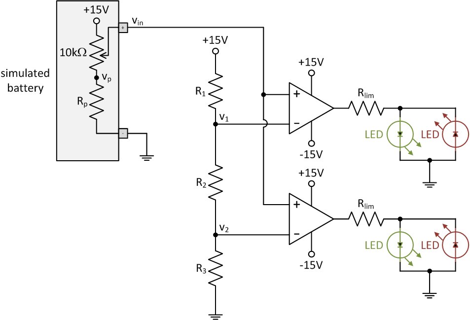
Figure 3: Voltage-level indicator
Note: The op-amp switching time from one rail to the other can be reduced by choosing an op-amp with a higher slew rate and by placing diodes around the op-amp such that the op-amp never enters saturation.
Revised MAR2015