EE 212L: Operational Amplifiers - Part II
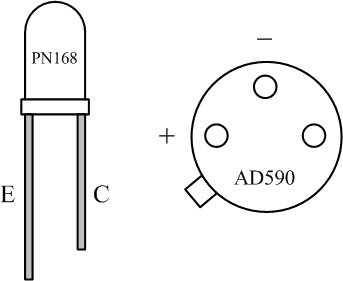
Objective: The purpose of this lab is to further understanding of the operational amplifier by building and studying amplifier circuits that convert currents into voltages. The National Semiconductor LF356 operational amplifier will be used as the basis for circuits that measure light and temperature. The sensors of interest and their connections are shown in Figure 1.
Pre-lab:
-
For the current-to-voltage converter shown in Figure 2, find the
relationship between the output voltage vo and input
current iin.
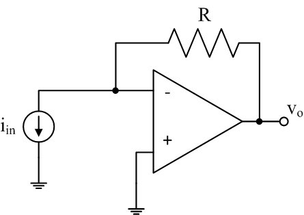
Figure 2: Current-to-voltage converter
Laboratory Procedure:
- Optical Detector
- Construct the optical detector circuit shown in Figure 3 using a
356 FET-input amplifier and the PN168 photo-transistor. (The 356
more closely approaches an ideal op amp but has the same pin
connections as the 741.)
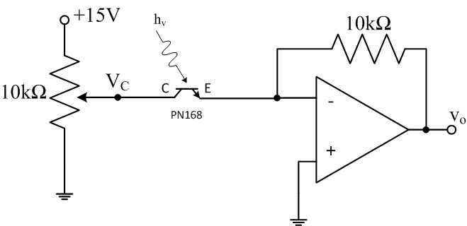
Figure 3: Optical detector circuit
- Vary the collector voltage VC to determine whether the PN168 acts more like a current source controlled by the incident light or variable resistor whose resistance changes with light.
- Observe and sketch the output waveform when VC is around 8V, making sure to note the location of 0V.
- Confirm that the output is caused by light incident upon the phototransistor. What is the source of the time varying light incident on your detector? (Hint: Measure its frequency.) Test your hypothesis by disabling the offending light source. Is there still a residual light level? What is its source?
- The spec sheet for the PN168 says that 500 lux incident light intensity produces 3mA collector current with VC = 8V. Use this to estimate the incident light intensity. Compare this with the intensity of direct sunlight (sunlight intensity = 10,000 to 100,000 lux).
- Construct the optical detector circuit shown in Figure 3 using a
356 FET-input amplifier and the PN168 photo-transistor. (The 356
more closely approaches an ideal op amp but has the same pin
connections as the 741.)
- Temperature Sensor
- Construct the temperature sensing circuit shown in Figure 4
using an Analog Devices Model AD590 temperature sensor. This is a
two-terminal device that behaves as an ideal current source of
1μA per degree Kelvin over the temperature range -55 to +150
degrees C.

Figure 4: Temperature sensing circuit
- View the output voltage on your scope to verify that it is a DC level only. Use a multimeter to accurately measure the output DC voltage.
- What room temperature does your reading imply? Compare with the room temperature reading from a thermometer.
- Check to see how much of the output voltage is due to the amplifier itself by replacing the sensor with a source of zero current.
- What is the sensitivity of the above circuit (Volts per degree Kelvin)?
- How could the sensitivity be increased?
- Approximately how much could the sensitivity be increased without saturating the amplifier output?
- Construct the temperature sensing circuit shown in Figure 4
using an Analog Devices Model AD590 temperature sensor. This is a
two-terminal device that behaves as an ideal current source of
1μA per degree Kelvin over the temperature range -55 to +150
degrees C.
- Temperature Sensor with Bias Adjustment
- Greater sensitivity can be obtained using a summing
configuration of the op-amp circuit to cancel out the sensor's
current at room temperature, as shown in Figure 5. Add the +15V
input section to your circuit keeping Rf unchanged
and choose Rc so that the sensor's current can be
cancelled at room temperature using the mid-range of the
potentiometer's voltage Vp.
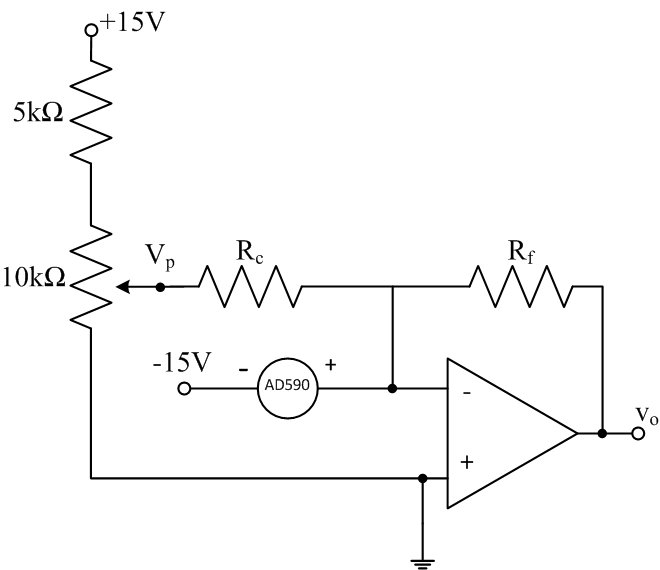
Figure 5: Modified temperature sensing circuit
- Precisely zero vo by adjusting the potentiometer. Is Vp what you expected?
- Calculate the feedback resistance Rf required to obtain a sensitivity of 0.5V per degree C and change Rf to this value. Make sure that the output is still adjusted for 0V DC at room temperature. Why should the output stay near 0V DC even though Rf has been changed?
- Check the operation of the updated circuit by holding the transducer between your thumb and forefinger. What temperature increase do you register? Normal body temperature is 37 degrees C, and a person with 'warm' hands registers about 28-30 degrees C. Do you have warm or cold hands? (This may say something about how relaxed you are in doing this lab, or how cold the room is.)
- Greater sensitivity can be obtained using a summing
configuration of the op-amp circuit to cancel out the sensor's
current at room temperature, as shown in Figure 5. Add the +15V
input section to your circuit keeping Rf unchanged
and choose Rc so that the sensor's current can be
cancelled at room temperature using the mid-range of the
potentiometer's voltage Vp.
Revised MAR2015