EE 212L: Introduction to Operational Amplifiers
Objective: The purpose of this lab is to build and study amplifier circuits that use the National Semiconductor LM741 operational amplifier.
Pre-lab:
-
For the inverting, summing amplifier shown in Figure 1, find the
relationship between the output voltage vo and inputs
va, vb.
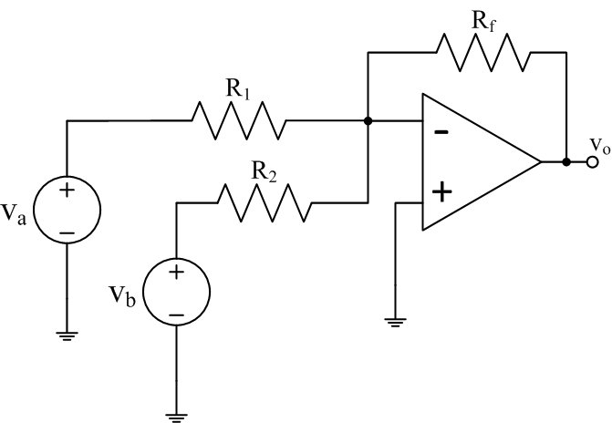
Figure 1: Summing amplifier
- For the circuit shown in Figure 4, find the following:
- The input impedance to the right of v1. This is typically done by taking the ratio of applied (input) voltage to induced current.
- The output impedance of the amplifier circuit. Note output impedance is the same at Thevenin's (equivalent) impedance.
- For the circuit shown in Figure 5, find the following:
- The voltage gain (ratio of output voltage vo to input voltage vS) of this circuit.
- The input impedance of this circuit.
- The output impedance of this circuit.
Laboratory Procedure:
- LM741 specifications from data sheet
- Give the data sheet for the LM741 op-amp a quick review noticing all the associated specifications.
- Sketch the pin-out (connection diagram) for the LM741. Show this diagram to your lab instructor to make sure all the connections are understood before proceeding (wrong connections will likely damage the op-amp).
- How is the location of pin 1 denoted on the integrated circuit?
- What are the absolute maximum ratings for the supply voltages used to power the op-amp?
- What is the typical open-loop gain of the op-amp (this is what we assume to be infinite in our ideal assumptions)?
- What is the short-circuit current, i.e., the maximum current the op-amp can provide?
- Inverting Amplifiers
- Wire up an inverting amplifier with an input resistance of 1kΩ and a gain of -10 as shown in Figure 2. Use a LM741 op-amp with supply voltages of plus and minus 15V. Employ good breadboard technique by using the bus lines on your breadboard for each of the supply voltages and ground.
- Vary the DC level of the op-amp input by turning the 10kΩ pot and take a couple of measurements to confirm that the amplifier is working as as expected.
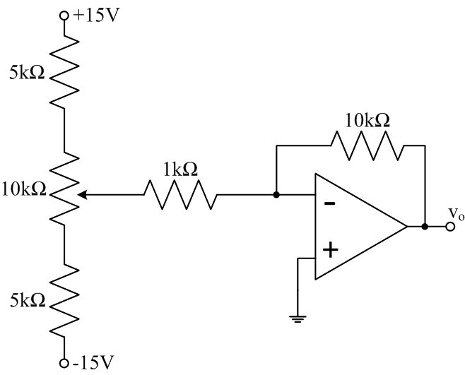
Figure 2: Inverting amplifier with (adjustable) constant input
- Add a 1kHz, 1Vp-p sine wave (shown as vs) to the amplifier input as shown in Figure 3.
- Measure the gain for several input amplitudes and compare with the theoretical gain.
- Confirm that the amplifier inverts the input by displaying both input and output sine waves on the scope (sketch waveform).
- Vary the DC level of the input by turning the 10kΩ pot and confirm that the amplifier is summing the two inputs.
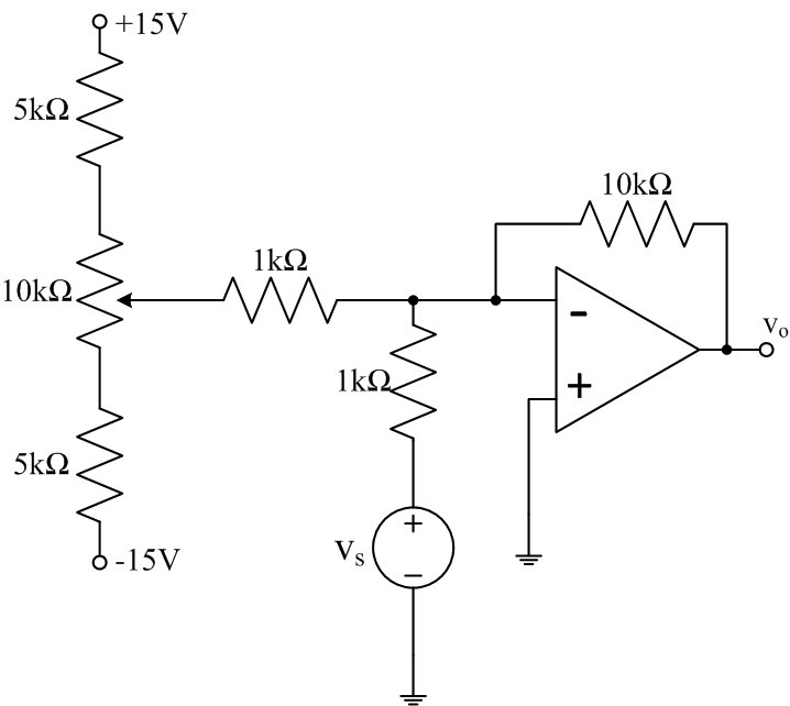
- Remove the DC input and apply only the 1kHz, 1Vp-p
sinusoidal input through an additional 1kΩ resistor as
shown in Figure 4.
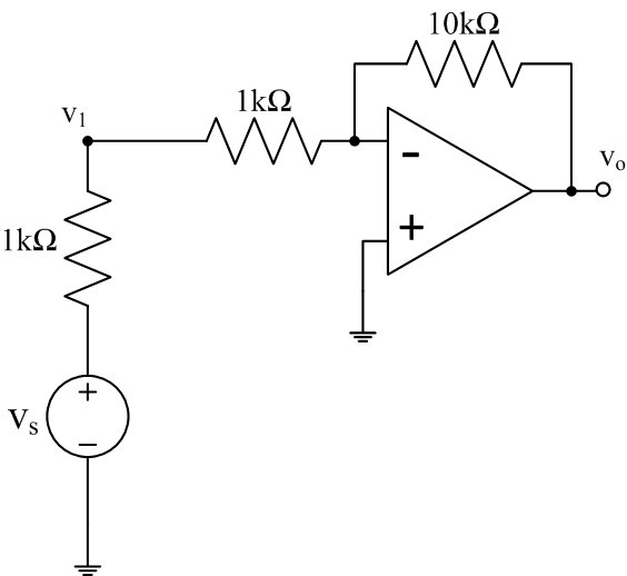
Figure 4: Inverting amplifier with sinusoidal input
- Calculate the amplifier circuit's input resistance looking into the amplifier circuit from the node labeled v1, at 1kHz, using the node voltages vS and v1. Why use this size of resistor?
- Measure (or try to) the output resistance of the amplifier circuit by representing it with a Thevenin equivalent circuit that can be found by putting a 1kΩ resistor from the output to ground and noting how much the output voltage changes. The change in the output voltage can be thought of as a voltage divider between Rout and the 1kΩ resistor. Why use this size of resistor?
- Increase the input amplitude to determine the voltage levels at which the output 'saturates'. How do these voltages compare to the supply voltages?
- Non-Inverting Amplifier
- Wire up the non-inverting amplifier shown in Figure 5. What is
the amplifier's voltage gain?
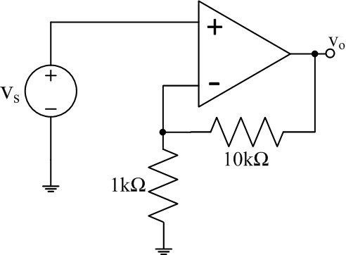
Figure 5: Non-inverting amplifier
- Measure its input resistance, at 1kHz, by putting a 100kΩ or 1MΩ resistor in series with the input vS. Why use this size of resistor?
- Does this configuration maintain the low output impedance you measured for the inverting amplifier?
- Wire up the non-inverting amplifier shown in Figure 5. What is
the amplifier's voltage gain?
- Follower
- Build a follower with the LM741 op-amp as shown in Figure
6. Check its performance, in particular measure (if possible)
Zin and Zout
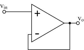
Figure 6: Voltage follower
- Build a follower with the LM741 op-amp as shown in Figure
6. Check its performance, in particular measure (if possible)
Zin and Zout
© Copyright 2004 New Mexico Institute of Mining and Technology
Revised FEB2015