EE 212L: Power Factor Correction
Objective: The purpose of this lab is to use power factor correction (via a capacitor) to change a load's behavior such that it appears purely resistive, i.e., had a power factor of 1.
Pre-lab:
-
For the circuit shown in Figure 1 below, determine the following:
- impedance ZL of the load
- power factor angle of the load
- power factor of the load
- complex power absorbed by the load
- expected time shift between the load's voltage and current
- Determine the value of a capacitor C that when placed in parallel with the original load impedance (see Figure 2) yields an equivalent power factor of 1. What is the value of this equivalent impedance? What relationship do we expect between the compensated load's voltage and current.
Laboratory Procedure: Recall that average power absorbed by a device or circuit is P = (1/2)VIcos(θ) W where V, I are the amplitudes of voltage and current, respectively, and θ = φV - φI is the phase difference between the element's sinusoidal voltage v(t) and current i(t). To obtain the most efficient use of the current delivered to a device or circuit, it is desired that the load voltage and current be in phase (θ = 0 and pf = 1).
- Investigate inductive load
- An inductor is a coil of wire and wire has resistance. Measure the resistance of your 0.47mH inductor. If this resistance is significant include it your calculations.
- Construct the following circuit.
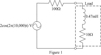
Figure 1: Circuit with uncompensated load
- Experimentally determine the load's impedance ZL, power factor angle θ, power factor pf, and complex power using voltage and current measurements. Compare these to your predicted values found in the prelab.
- Load power factor correction
- Add a capacitor of the value determined in the prelab in
parallel with the original load as shown in Figure 2. Note the
value of the capacitor may need to be updated based upon the
resistance of the inductor.
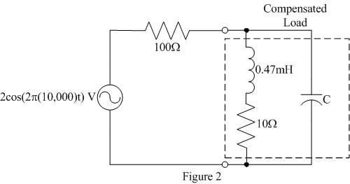
Figure 2: Circuit with compensated load
- Verify that your power factor correction is working. How do the compensated load's voltage, current and impedance compare to that predicted?
- Normally, it isn't a good idea to change a circuit with input and power applied, but carefully insert and remove the capacitor while watching the load's voltage and current to easily see the effect of the compensation.
- Does your load compensation work at other frequencies other than 10kHz? Investigate this both mathematically and experimentally. Is there a difference in the load's behavior as frequency is increased versus decreased?
- Add a capacitor of the value determined in the prelab in
parallel with the original load as shown in Figure 2. Note the
value of the capacitor may need to be updated based upon the
resistance of the inductor.
© Copyright 2004 New Mexico Institute of Mining and Technology
Revised FEB2015