EE 212L: Sinusoidal Signals and the Oscilloscope
Objective: The purpose of this lab is become acquainted with the operation of an oscilloscope, function generator and AC function of your multimeter by investigating the sinusoidal responses of simple circuits.
Pre-lab:
- What is the relationship between peak-to-peak, Vp-p, amplitude, Vp, and root-mean-square, Vrms values?
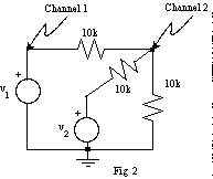
- Via superposition, find the voltage at the node labeled Channel 2 in figure 2 in terms of v1 and v2.
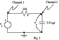
- For the circuit shown in figure 3 with v1
= sin(2π(1000)t), R = 10kΩ, C unknown, and vo
delayed with respect to v1 by 0.1ms, determine
- phase shift between v1 and vo in radians and degrees,
- value of capacitance C for this circuit, and
- expression for vo.
Laboratory Procedure:
- The Oscilloscope as a Voltmeter
- Turn on the oscilloscope, display the trace for Channel (Ch) 1, and check trigger settings (trigger menu => edge, rising (slope), CH1 (source), auto (mode), DC (coupling)).
- Apply 0V then 5V to Ch 1 and compare the measured voltages to multimeter readings. More accurate measurements may be obtained by using cursors (cursor => voltage or time (type), CH1 or CH2 (source), then select cursor 1 or 2 from the oscilloscope and turn the multipurpose knob to adjust the cursors, or select 'measure' mode located along top of oscilloscope.
- Sine Waves on the Oscilloscope
- Apply a small amplitude (less than 5V), 1kHz sine wave from your function generator to Ch 1. Adjust the trigger controls to get a stable waveform display.
- Experiment with the trigger level, slope, and other controls. Finish with the display being triggered as the waveform crosses zero while rising.
- Experiment with the time base control. Adjust the sine wave frequency on the frequency generator to be exactly 1kHz. Use the cursors to measure the period. What frequency is displayed on the oscilloscope? Is the reading what you expect? Check the period of ten cycles.
- Adjust the amplitude of the sine wave to be 1V peak-to-peak (p-p).
- Measure the amplitude of the sine wave using the oscilloscope. What error do you estimate for this amplitude measurement? Measure the amplitude with the AC Volts function of the multimeter. How should and how do these numbers compare?
- Voltage Divider and Superposition
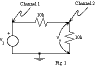
- Consider the circuit in figure
1.

- Wire up the circuit shown in figure 1 where v1 is a 5V p-p 1kHz sine wave.
- Display v1 on Ch 1 and output of this voltage divider, vo, on Ch 2. Compare the voltages and phases. Repeat at 10kHz.
- Consider the circuit in figure 2 where a source and resistor
have been added to the circuit shown above in figure
1.

- Let v2 be a 5V DC source and use superposition to analytically solve for the output voltage, vo (labeled Channel 2).
- Wire up the circuit shown in figure 2 with v2 a 5V DC source.
- Ground the inputs of both sources and adjust the trace positions for channels 1 and 2 so that the oscilloscope displays a position of 0 Volts on both channels, to see where 0V DC is on the scope. Now connect both sources to the circuit and measure the output voltage vo. Is vo what you expected it to be?
- Connect v2 to ground instead of 5V, and record how the vo waveform changes. Reconnect v2 to 5V and record the average value of vo as you slowly decrease v1 to 0V.
- Return v1 to a 5V p-p sine wave and AC couple the scope inputs. Notice that the DC level is removed when the scope input is AC coupled. This is because a capacitor has been connected in series with the input.
- Consider the circuit in figure
1.
- Phase Measurements
- Consider the RC circuit shown in figure
3.

- Wire up the RC circuit shown in figure 3 with v1 a 1kHz 5V p-p sine wave.
- Observe the input v1 and output vo on the two channels, and compare their amplitudes and phases.
- Measure R with an ohmmeter, and calculate C from the ratio of amplitudes and from the phase shift. Compare your calculated values of C with the value labeled on the capacitor. Repeat at several frequencies including 100Hz and 10kHz. At what frequency does the measured value of C compare best with its labeled value? What is the maximum phase shift you can get?
- Consider the RC circuit shown in figure
3.
- Summary
- Before you go, make sure you understand the following
features of the oscilloscope:
- Horizontal controls: Time per division, trigger level, trigger slope, auto vs. normal sweep.
- Vertical controls: Volts per division, fine vs. course scaling, AC vs. DC coupling.
- Measurements: Voltage, phase angle via time shift, use of cursors.
- Before you go, make sure you understand the following
features of the oscilloscope: