EE 212L: Multiple Feedback Topology Band-pass Filter and the Fourier Series
Objective: The purpose of this lab is to design a band-pass filter that selects a harmonic of a square or triangle wave to produce a sinusoid.
Pre-lab:
- Calculate the trigonometric Fourier Series of a 1kHz square wave that varies equally (i.e., 50% duty cycle) between 0V and 2V.
- For the Multi Feedback Topology Band-pass Filter circuit shown
in Figure 1 below, confirm the transfer function H(s) given below.
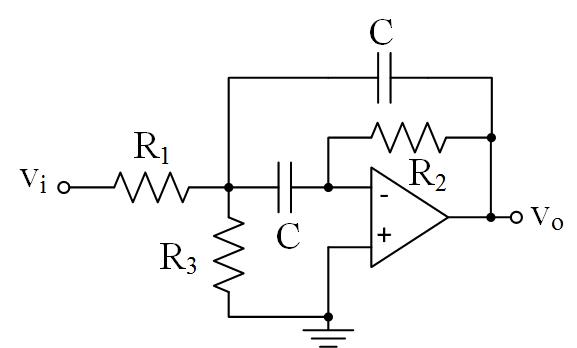
Figure 1: Multiple Feedback Topology Band-pass Filter (MFT BPF) 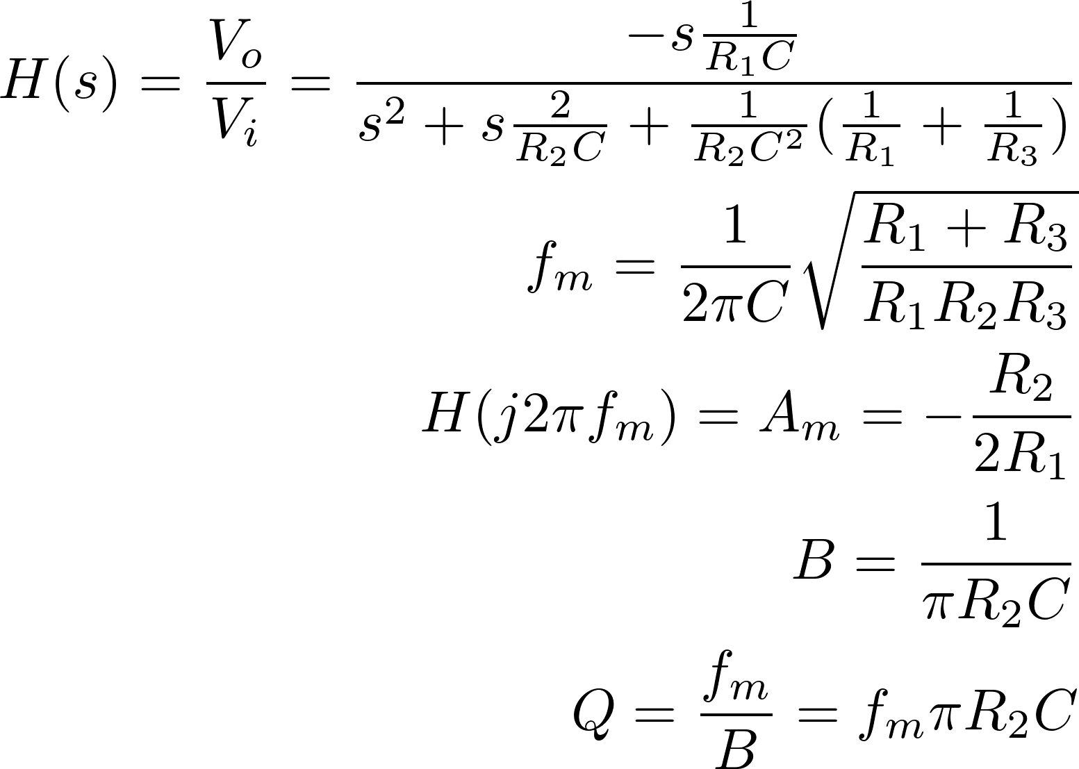
where the filter's parameters are- fm: middle (center) frequency in Hz
- Am: gain at middle frequency, fm, in V/V
- B: bandwidth between half power frequencies in Hz
- Q: quality factor.
- Determine parameters for the MFT BPF such that it will pass only the first harmonic of the square wave's Trigonometric Fourier Series, and the output will have an amplitude of one. Values for resistors should roughly stay within the range of 1kΩ to 100kΩ and values for capacitors should roughly stay within the range of 1nF to several µF.
- Plot the frequency response of the designed filter using values selected for resistors and capacitors, and the transfer function to confirm your design. Note you'll be confirming this behavior in lab, so bring a useful copy of the frequency response.
Laboratory Procedure:
- Build the circuit as designed in the pre-lab.
- Confirm the filter performs as designed by sketching its amplitude response (make sure to check key values used in the design) found through measurements and compare to that predicted in the pre-lab.
- Use the function generator to create a square wave of the type
noted in the pre-lab.
- Check that the square wave looks as expected on the oscilloscope and then use the Fast Fourier Transform (FFT) under the oscilloscope's Math Options to display the square wave's amplitude spectrum. How does this amplitude spectrum compare to that of the trigonometric Fourier Series?
- Use the square wave as the input to your filter, and sketch the input and the output. Is your output the sinusoid (amplitude and frequency) expected? What would change if a low-pass filter with the first harmonic in the pass-band was implemented instead of the band-pass filter?
- With same square wave as input, can you change the filter's middle frequency to view the third (second nonzero) harmonic? This may be possible by changing one resistor, so give it a try and comment as to why it did or didn't work.
© Copyright 2017 New Mexico Institute of Mining and Technology
Revised APR2017