EE 212L: Phase Shifter Circuit and Three-phase Power
Objective: The purpose of this lab is to utilize op-amp-based phase shifter circuits to build a (simulated) three-phase balanced power system and confirm its behavior.
Pre-lab:
- Determine the transfer function H(jω) =
Vo/Vi for each phase-phase shifting circuit
shown below. Calculate the magnitude and phase angle of both
transfer functions in terms of R, Rp, C and ω.
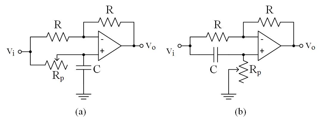
Figure 1: Phase shifter circuits
- Design (and show via a sketch including pin numbers for
op-amps) a three-phase power system using a function generator as
one sinusoidal source and phase-shifting circuits to act as the
other two sources. The three-phase circuit is to have the
following features.
- Three sinusoidal sources of equal amplitude (1.2Vrms), 120deg phase shift between them, and common frequency of 1kHz. This can be achieved by implementing phase shifting circuits with appropriate values for resistors and capacitors.
- The common (ground) of the inputs will serve as the neutral for the three sources.
- Three line resistances of 100Ω each will connect the sources to three loads of 1kΩ each in a Y-configuration. The center of the Y-configured load will serve as the load's neutral.
- Place a return line (also a 100Ω resistor) between the neutral at the source and neutral at the load.
Laboratory Procedure:
- Have your instructor check your design presented as a neat sketch.
- Build the three-phase circuit using sinusoidal sources of
amplitude 1.2Vrms and frequency 1kHz. The four lines
(including a return) are 100Ω resistors and the three
Y-connected loads are 1kΩ resistors.
- Make adjustments to ensure the system is balanced, i.e., proper amplitudes and phase angles at the sources.
- Use a voltmeter to measure the line-to-line rms voltages and line-to-neutral rms voltages at the source and load. Compare these values to those expected. Why are we using the voltmeter versus the oscilloscope?
- Measure the rms voltage between the sources' neutral and the loads' neutral. What does this voltage indicate about the current in the return wire? What should the current be in the return wire for a balanced circuit? Make adjustments to better balance the circuit if needed.
- Take appropriate measurements and calculate the (four) line currents as rms.
- Unbalance the load by replacing one of the 1kΩ resistors with a 2kΩ resistor. Remeasure the line currents paying particular attention to the change in the return wire's current.
Revised APR2017