next up previous
Next: 3.2 Using Quartus Up: 3 Supplementary Material Previous: 3 Supplementary Material


3.1 Introduction to Verilog

  1. In order to write an Verilog HDL description of any circuit you will need to write a module which is the fundamental descriptive unit in Verilog. A module is a set of text describing your circuit and is enclosed by the keywords module and endmodule.
  2. As the program describes a physical circuit you will need to specify the inputs, the outputs, the behavior of the circuit and how the gates are wired. To accomplish this, you need the keywords input, output, and wire to define the inputs, outputs and the wiring between the gates, respectively.
  3. There are multiple ways to model a circuit
  4. A simple program modeling a circuit (see Figure 2) at the gate-level, is provided below.

    Figure 2: Simple Circuit
    \begin{figure}\begin{center}
%
\input{simple_circuit.pstex_t}
\end{center} \end{figure}


    \begin{program}
% latex2html id marker 64\begin{verbatim}module simple_cir...
...{Simple program in Verilog modeling a circuit
at the gate-level}
\end{program}

  5. As seen above the outputs come first in the port list followed by the inputs.

  6. Single line comments begin with //

  7. Multi-line comments are enclosed by /* */

  8. Verilog is case sensitive.

  9. A simple program modeling a circuit using dataflow, is provided below.

    \begin{program}
% latex2html id marker 72\begin{verbatim}module simple_cir...
...n{Simple program in Verilog modeling a circuit
using dataflow}
.
\end{program}

  10. You can identifiers describing multiple bits known as vectors. For example you may write Program 2 as


    \begin{program}
% latex2html id marker 82\begin{verbatim}module simple_cir...
...am in Verilog modeling a circuit
using dataflow using vectors}
.
\end{program}

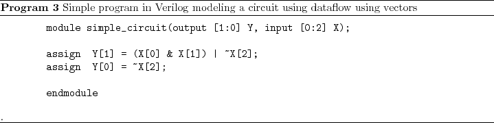
    In this example, we have the input as three bits representing A, B, C and we have denoted them as [0:2] X which means we have three bits with the index 0 representing the MSB. We could have specified it as [2:0] X in which case the index 2 represents the MSB.

  11. Given an identifier [7:0] X you can assign it values by

    assign [7:0] X = 8'b00101011;

    where the 8'b specifies that we are defining an 8-bit binary number and 00101011 is that 8-bit binary number. You can also assign parts of the number as

    assign [2:0] X = 3'b101;

    which assigns only the last three bits of X.


next up previous
Next: 3.2 Using Quartus Up: 3 Supplementary Material Previous: 3 Supplementary Material
Copyright © 2008, Electrical Engineering Department, New Mexico Tech
Last Modified 2008-09-16