Next: 3 Supplementary Material
Up: Lab 5: Arithmetic Logic
Previous: 1 Prelab
- Design the ALU using Verilog. (Make sure you deal with any unused
bit combinations of the ALU_CTL lines).
- Simulate the ALU and test different combinations of DATA and
ACCA.
- Program your ALU code into your CPLD.
- Create another program that will call your ALU module. In this
module read external inputs for ACCA and DATA as well
as the ALU_CTR. Output your results on two 7-segment
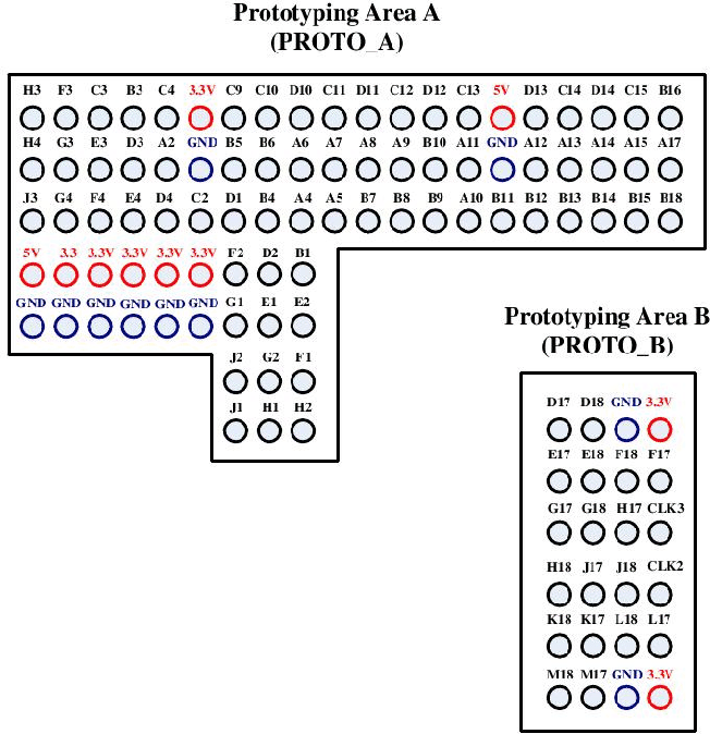
displays (Pinout of the MAX II micro board is shown in
Figure 2).
Figure 2:
I/O map of prototyping areas
|
|
Copyright © 2008, Electrical Engineering Department, New Mexico Tech
Last Modified 2009-09-29