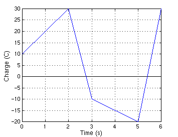
Figure P1-8 shows a plot of the net positive charge flowing in a wire versus time. Sketch the corresponding current during the same time period.
The current through a device is given by i(t) = 0.05t A. How many coulombs enter the device between time t = 0 s and t = 5 s?
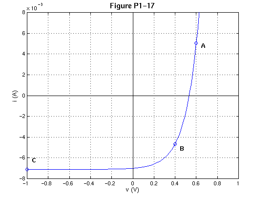
A two-terminal device has the current versus voltage characteristics shown below. Assuming the passive sign convention,
- Determine the device power when it operates at point A and state whether the device is absorbing or delivering power.
- Repeat part (a) when the device operates at points B and C.
- Identify the operating point on the curve (it could be a point other than A, B, or C) at which the device delivers the most power.
The voltage across and current through a two-terminal device are v(t) = 5 e-100t V and i(t) = -5e-100t mA.
- Find the power delivered by the device at t = 0, t = 5 ms and t = 25 ms.
- Find the total energy delivered by the device during the interval
 .
.
In complete darkness the voltage across and current through a two-terminal light detector are +5.6 V and +8 nA. In full sunlight the voltage and current are +0.9 V and +4 mA. Express the light/dark power ratio of the device in decibels (dB). (See Problem 1-6 for the definition of a decibel.)
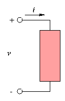
Figure P2-1 shows a general two-terminal element with voltage and current reference marks assigned. Find the unknown electrical variables when the element is
- A linear 10-k
 resistor with v = 12V.
- An ideal 10-mA current source with the arrow directed upward and p = 20 mW.
- An ideal 15-V voltage source with the plus terminal at the top and i = -8 mA.
- An ideal switch with i = -20mA.
A fuse contains a metal link that melts to create an open circuit when the current through the device exceeds IBLOW. When the current is less the IBLOW, the fuse acts like a fixed resistor RFUSE. For a certain fuse, IBLOW = 20 mA and RFUSE = 10
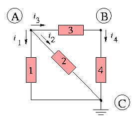
For the circuit in Figure P2-11,
- Identify the nodes and at least two loops.
- Identify any elements connected in series or in parallel.
- Write KCL and KVL connection equations for the circuit.
- If i1 = 6 mA and i2 -4 mA, find the other element currents.
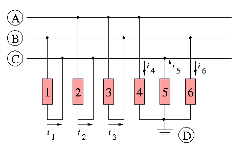
The circuit in Figure P2-15 is organized around the three signal lines A, B, and C.
- Identify the nodes and at least three loops in the circuit.
- Write KCL connection equations for the circuit.
- If i3 = 15 mA, i4 = -12 mA, and i5 = 5 mA, find the other element currents.
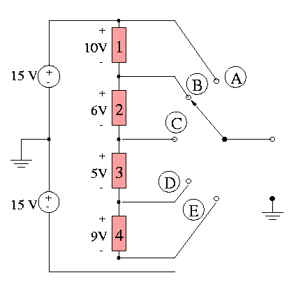
The circuit in Figure P2-17 is called a multitap voltage divider. Use KCL to find the output voltage when the switch is in position A, B, C, D, and E. Hint: The output voltage is defined relative to ground.
