EE 308 - LAB 6

Final version for 2000


HC12 Timer Interrupts

First we will explore the timer and the TCNT register. Then we will write a simple program which uses the timer overflow interrupt and the input capture interrupt. For the pre-lab you should write the program for Part 6 (which includes the program for Part 4).

1.
Connect your HC12 to your computer. At the D-Bug12 prompt, display the contents of the TCNT register. Do this several times. How do the values compare?

2.
Use D-Bug12 to modify the TSCR register to enable the counter. Repeat Part 1.

3.
Use D-Bug12 to modify the TSCR register to disable the counter. Repeat Part 1.

4.
Start with the following program, which is just a do-nothing infinite loop:
             #include <hc12.h>

             #define TRUE 1

             main()
             {
                 DDRA = 0xff;       /* Make all bits of Port A output */
                 PORTA = 0x00;
                 while (TRUE) 
                {
                    _asm("_wai");
                }
             }

Add a Timer Overflow Interrupt service routine to increment Port A. Answer the following questions:

(a)
Calculate how long it should take Port A to overflow. Measure this time. How long does it take Port A to overflow?

(b)
Change the prescaler so the TOF interrupt will occur every 32 ms. Calculate how long it should take Port A to overflow. Measure this time. How long does it take Port A to overflow?

(c)
What happens when you fail to clear the TOF flag as part of your TOF interrupt service routine? Check your conjecture by commenting this line out of your program and running the new program. When done, be sure to restore your program to clear the TOF flag.

5.
Connect one of your debounced switches to Input Capture 2 (Port T, Bit 2), as shown below:


Figure 1: Circuit to measure speed of button pushing.
\begin{figure}
\begin{center}
\epsfig{file=lab06_fig1.eps, width=6in}\end{center}
\end{figure}

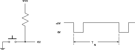
The right part of Figure 1 is what the signal to IC2 will look like if you push the pushbutton twice.

6.
Add to your program code to measure the time TR between the two falling edges of the signal in Figure 1. Set the prescaler so you can measure time differences up to 250 ms.

It is inconvenient to have to stop the HC12 and look at a memory location to determine what your result was. D-Bug12 has built in routines to write information to the terminal. This is documented in the application note Using the Callable Routines in D-Bug12 included with your HC12 board. In your program, TR should be a sixteen-bit unsigned number. D-Bug12 provides a C-like printf() function you can use to print information to the screen. The information below shows some examples of how to do this.

To use the D-Bug12 routines you will have to include the header file DBug12.h. This can be downloaded from the EE 308 homepage.

Here is a program to print hello, world to the terminal:

#include "DBug12.h"

main()
{
    DBug12FNP->printf("hello, world\n\r");
}

Here is a program to print an unsigned number to the screen in both hexadecimal and decimal:

#include "DBug12.h"

main()
{
    unsigned int x;

    x = 0xf000;
    DBug12FNP->printf("Hex:  %x, Decimal:  %u\n\r",x,x);
}

Add to your program a printf() function to print out the result - the number of timer ticks between pushes of the button. (Do not try to calculate the actual time as a floating point number. When you use floating point numbers the programs will be too large to load into the HC12 without using expanded memory.) You should write your program as an infinite loop so that after pressing the button twice your program will print out the result, the go wait for the next two presses.

7.
Test your program on your EVBU. See how fast you can push the switch twice.


Note: to compile a program with interrupts, be sure to have your interrupt vector array in a separate file called vector.c. Change you cc.bat program to look like this:

  cx6812 -vl -ax +debug crts.s %1.c vector.c
  clnk -o %1.h12 -m %1.map %1.lkf
  chex -o %1.s19 %1.h12
  clabs %1.h12

The interrupt vectors for DBug-12 start at address 0x0b10. To tell the linker to put the interrupt vector file at the right place, change your lkf file to look like this:

  # link command file for test program
  #
  +seg .text -b 0x0800 -n .text # program start address
  +seg .const -a .text          # constants follow code
  +seg .data -b 0x0900          # data start address
  crts.o                        # startup routine
  lab06.o                       # application program
  +seg .const -b 0x0b10         # interrupt vectors start here
  vector.o                      # file of interrupt vectors
  +def __stack=0x0A00           # stack pointer initial value


Bill Rison
2000-02-23