Figure 1: Block diagram for final project lab.
EE 308 -- LAB 12
Final Project
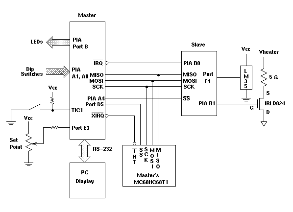
For your final project, you will use two HC11 boards as a temperature controller (Figure 1). The two boards will be connected together through their SPI ports, one board acting as master and the other as slave. The slave board will control the temperature of an oven. It will turn the oven heater element on and off in order to keep the oven at a constant temperature. It will send the temperature of the oven to the master board over the SPI interface. The master board will tell the slave board what temperature it wants the oven set at, and will display the temperature received from the slave on its LEDs.
Figure 1: Block diagram for final project lab.
The master board will have a pot connected to it, which will determine the temperature you want the oven to be. Turning the pot will change the oven set point.
The slave board will have an oven (power resistor) connected to it. It can control current through the resistor by turning on and off an FET switch. When the switch is on (+5 V on the FET gate), the oven will heat up. When the switch is off (0 V on the FET gate), the oven will cool down. An LM35 temperature sensor attached to the oven will measure its temperature. The slave board should receive the set point from the master board, turn on the heater if the temperature is above the set point, then turn off the heater if the temperature is below the set point.
Note that you should use two protoboards for power. One board should supply power for the HC11 boards and the power labeled Vcc in Figure 1. The other protoboard should supply the 5 V needed to power the oven heater. The reason for this is that the oven heater draws so much current that, if an HC11 board were connected to the same supply as the heater, when the heater turns on, the power supply voltage will drop below the 4.5 V needed to operate the HC11. Be sure to connect a common ground between the two boards.
Program the HC11s in the following way:
| PA 1 | PA 0 | PIA Port B Function |
|---|---|---|
| 0 | 0 | Oven Set Point |
| 0 | 1 | Oven Temperature |
| 1 | 0 | Up Counter |
| 1 | 1 | Turn Signal |
Table 1: PIA Port A inputs to control the PIA Port B functions.
Optional. Once you get this system working, program it into the EPROM version of the HC11 chip you received with your kit. We will discuss how to do this in lab. More information is given in this description