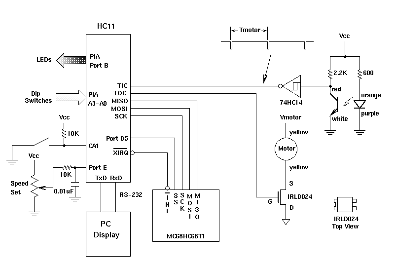
Figure 1: Block diagram for final project lab.
For your final project, you will use an HC11 board as a motor controller (Figure 1). A potentiometer connected to the HC11's A/D converter will be used to adjust a motor's speed. The HC11 will control the speed of the motor using pulse width modulation

Figure 1: Block diagram for final project lab.
The HC11 will have a pot connected to it, which will be used to set the motor speed. The speed of the motor should be 500 RPM at 0 volts, and 3,000 RPM at 5 V.
The HC11 will control the motor speed using pulse width modulation. It can control current through the motor by turning on and off an FET switch. The duty cycle (the percent of time the switch is turn on) controls the motor speed. A 100% duty cycle will yield maximum speed (about 3,000 RPM when Vmotor = 7 V), and duty cycles of about 10% or less will yield zero speed. An optical sensor attached to the motor will measure its speed. An LED sends light to an opto-transistor -- when the light from the LED can reach the transistor, the transistor will be turned on, current will flow through the 2.2 k Ohm collector resistor, and the voltage at the collector will be about 0.5 V. A blade on the motor will momentarily block the light from the LED from reaching the opto-transistor. When this happens, the transistor will turn off, very little current will flow through the transistor, and the voltage at the collector will be about 5 V. This collector voltage is inverted and turned into a clean digital signal by the 74HC14 Schmitt trigger. By using a timer input capture pin to measure the period of the signal from the Schmitt trigger, you can determine the speed of the motor.
The HC11 should slowly increase the duty cycle of the pulse width modulation until the speed of the motor equals that determined from the set point. When the the set point is reduced, the HC11 should slowly decrease the duty cycle until the set point is reached. How to do this will be discussed in class.
Program the HC11 in the following way:
| PA2 | PA1 | PA0 | | PIA Port B Function |
|---|---|---|---|---|
| 0 | X | 0 | | Motor Set Point |
| 0 | X | 1 | | Motor Speed |
| 1 | 0 | 0 | | Up Counter |
| 1 | 0 | 1 | | Down Counter |
| 1 | 1 | 0 | | Flasher |
| 1 | 1 | 1 | | Turn Signal |
Table 1: PIA Port A inputs to control the PIA Port B functions.